Endovascular aneurysm devices, systems, and methods

a technology of endovascular aneurysm and endovascular aneurysm, applied in the field of endovascular aneurysm devices, systems, and methods, can solve the problems of aneurysm formation, aneurysm growth, and the formation of aneurysms, and achieve the effects of reducing the risk of aneurysm formation

Inactive Publication Date: 2007-03-29
MEDTRONIC VASCULAR INC
View PDF103 Cites 960 Cited by
  • Summary
  • Abstract
  • Description
  • Claims
  • Application Information

AI Technical Summary

Benefits of technology

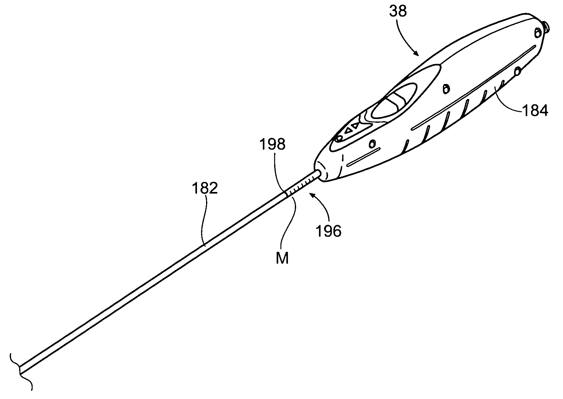
[0008] One aspect of the invention provides a system comprising a guide defining an access path into a vessel or hollow body organ and a fastener applier comprising a catheter sized and configured for introduction along the access path to a site targeted for implantation of at least one fastener. The guide includes a distal region with terminus. The fastener applier includes an actuated member that is selectively operable to generate an implantation force to implant the at least one fastener within tissue at the site. According to this aspect of the invention, the catheter includes indicia visible to a naked eye to mark when the actuated member rests at a desired distance along the access path short of the terminus of the distal region and is therefore still out of contact with tissue. The visible indicia makes it possible for the physician, without resort to fluoroscopic visualization or other visualizations techniques that augment human sight, to always know whether the fastener is within or outside the guide.

Problems solved by technology

The weakening of a vessel wall from damage or disease can lead to vessel dilatation and the formation of an aneurysm.
Left untreated, an aneurysm can grow in size and may eventually rupture.
The rupture of an aortic aneurysm results in massive hemorrhaging and has a high rate of mortality.
The prosthesis for these procedures are usually unsupported woven tubes and are typically made from polyester, ePTFE or other suitable materials.
However, these procedures require a large surgical incision and have a high rate of morbidity and mortality.
In addition, many patients are unsuitable for this type of major surgery due to other co-morbidities.
These prosthesis attachment means do not provide the same level of attachment when compared to suture and can damage the native vessel upon deployment.

Method used


Image

  • Endovascular aneurysm devices, systems, and methods
  • Endovascular aneurysm devices, systems, and methods
  • Endovascular aneurysm devices, systems, and methods

Examples


Embodiment Construction

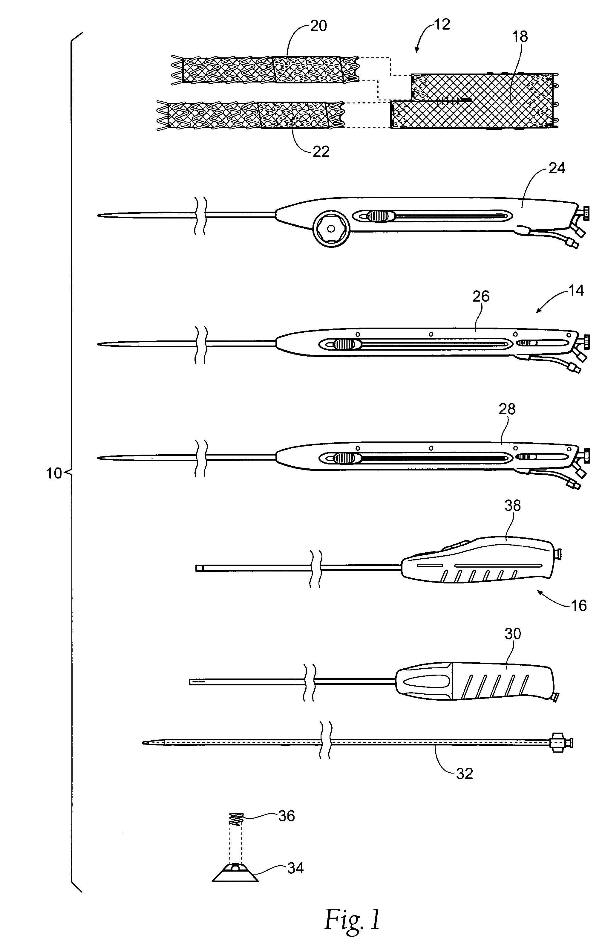
[0044] This Specification discloses various catheter-based devices, systems, and methods for delivering and implanting radially expandable prostheses in the body lumens. For example, the various aspects of the invention have application in procedures requiring the repair of diseased and / or damaged sections of a hollow body organ and / or blood vessel. The devices, systems, and methods that embody features of the invention are also adaptable for use with systems and surgical techniques that are not necessarily catheter-based.

[0045] The devices, systems, and methods are particularly well suited for treating aneurysms of the aorta that primarily occur in the abdominal region, usually in the infrarenal area between the renal arteries and the aortic bifurcation, as well as aneurysms that also occur in the thoracic region between the aortic arch and renal arteries. For this reason, the devices, systems, and methods will be described in this context. Still, it should be appreciated that the...


PUM


Abstract

Devices, systems, and methods for implanting prostheses in the body lumens rely on tacking or anchoring the prostheses with separately introduced fasteners. After initial placement, a fastener applier system is introduced within the expanded prostheses to deploy a plurality of fasteners to at least one prosthesis end. The fasteners are usually helical fasteners which are releasably restrained on the fastener driver, and are delivered by rotation of the fastener driver. The fasteners may be applied singly, typically in circumferentially spaced-apart patterns about the interior of at least one end of the prosthesis. A lumen extension or lumens may be coupled to the prosthesis to extend the reach of the prosthesis within the implantation site. Fasteners may also be applied to the lumen extensions.

Description

RELATED APPLICATIONS [0001] This application is a continuation-in-part of co-pending U.S. patent application Ser. No. 11 / 254,116, filed Oct. 20, 2005, and entitled “Devices, Systems, and Methods for Prosthesis Delivery and Implantation,” which is incorporated herein by reference. This application also is a continuation-in-part of co-pending U.S. patent application Ser. No. 10 / 692,283, filed Oct. 23, 2003, and entitled “Prosthesis Delivery Systems and Methods,” which claims the benefit of U.S. Provisional Patent Application Ser. No. 60 / 488,753, filed Jul. 21, 2003, and entitled “Endoprosthesis Delivery Systems and Methods.” This application also is a continuation-in-part of co-pending U.S. patent application Ser. No. 10 / 786,465, filed Feb. 25 2004, and entitled “Systems and Methods for Attaching a Prosthesis Within a Body Lumen or Hollow Organ.” This application is also a continuation-in-part of co-pending U.S. patent application Ser. No. 11 / 693,255, filed Jun. 24, 2005, entitled “Mu...

Claims


Application Information

Patent Timeline
Patent Type & Authority Applications(United States)
IPC IPC(8): A61F2/06
CPCA61B17/064A61F2/89A61B2017/0649A61B2017/0688A61F2/0095A61F2/064A61F2/07A61F2/954A61F2/966A61F2002/067A61F2002/075A61F2002/30617A61F2002/9511A61F2002/9517A61F2250/0097A61B17/068A61F2/9517A61M39/06A61M2039/062A61M2039/066
Inventor BOLDUC, LEECHIANG, ANDREW L.JEN, JIMMYSTAFFORD, JOSHUA
Owner MEDTRONIC VASCULAR INC
Why Eureka
Try Eureka