Pliable handle

a handle and pliable technology, applied in the field of handles, can solve the problems of gel leakage, high cost, and long assembly time, and achieve the effects of fast assembly, simple structure and secure sealing

Inactive Publication Date: 2007-04-05
XIAMEN JUNDIAN HOUSE OMAMENTS
View PDF11 Cites 21 Cited by
  • Summary
  • Abstract
  • Description
  • Claims
  • Application Information

AI Technical Summary

Benefits of technology

[0005] The present invention provided a pliable handle that ha...

Problems solved by technology

Because the movement of the gel is too slow like oil, even a small gap would lead to the leak of the gel.
But in this case, the cost is too expensive and it takes much time for assembling.
For keeping components close to each other, we must machine the components exactly, so the cost is too much.
1, although using the thread outer shoulder to press on the outer sheath which is on the top of the core member, the outer shoulder will loose after using the handle for a long time, and it can not prevent gel-leaking.
Because of using the 2 nozzles of the inj...

Method used


Image

  • Pliable handle
  • Pliable handle
  • Pliable handle

Examples


first embodiment

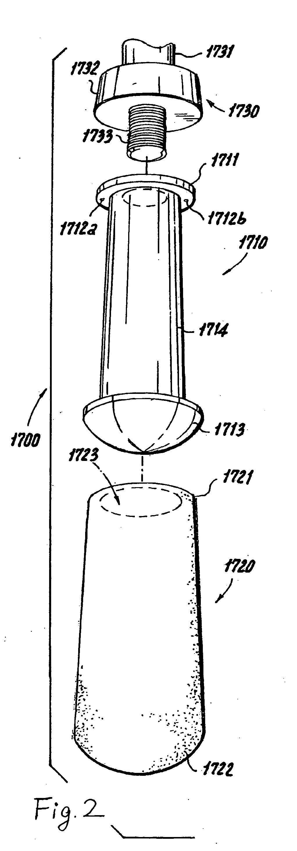
[0041] The first embodiment, the embodiment of the pliable handle of the present invention can be secured to a device, such as the pole of the walking stick, gold club, ski stick, tennis racket, battledore, and all kinds of umbrellas. As FIG. 3 shows, the pliable handle include a core member 11, a outer sheath, a proximal cap 13, and the gel 14.

[0042] The core member 11 is stick-shaped, there is a bore 110 for central rod on the top of the core member. There is the outwards extending flange 111 on the top of the core member 11; the outwards extending flange 111 is divided into two portions -upper portion and lower portion by the annular groove 112 on the center of the outwards extending flange 1. There is a protuberance 113 above the center of the outwards extending flange 111; the protuberance 113 has the thread portion.

[0043] The outer sheath 12 has an opening on top and a closed bottom, there is a inwards extending flange 121 in its opening; there is a annular flange 122 which c...

second embodiment

[0053] The second embodiment, as FIG. 6FIG. 7 shows, the luminous pliable handle including the core member 21 the outer sheath 22 and gel body 24 and luminous equipment 23.

[0054] The core member 21 is stick-shaped, there is a trapezium-shaped bore 213 downwards on the top of the core member. The outwards extending flange 221 having trumpet-shaped is on the top of the core member 21; an annular groove 212 is on the outwards extending flange 211.

[0055] The outer sheath 22 has an opening on top and a closed bottom, there is a inwards extending flange 221 in its opening; there is a annular flange 222 which corresponds with the annular groove 212 on the core member 1 below the inwards extending flange 221.

[0056] The luminous equipment 23, including batteries 231, which is disposed on the place trapezium-shaped bore 213 the core member 21, the luminophor 232 is set on the place which is under the trapezium-shaped bore 213.

[0057] During the assembly process: as FIG. 8 shows,

[0058] Meas...


PUM


Abstract

A pliable handle includes a core member, an outer sheath, and gel disposed between the core member and the outer sheath. There is an outer annular flange around its top. The outer sheath has an opening on its top and a closed bottom, an inner annular flange on its top; and the outer sheath is disposed about the core member. Below the inner annular flange of the outer sheath and the outer annular flange of the core member define the gap portion, which is filled with gel. There is an annular flange which corresponds with the annular groove on the core member below the inner annular flange of the outer sheath. The present pliable handle can be secured to walking sticks, golf clubs, ski poles, tennis rackets, battledores, and umbrellas.

Description

FIELD OF THE INVENTION [0001] The present invention generally relates to handles of hand-held devices, sports equipments or rackets. BACKGROUND TECHNOLOGY [0002] Handles of hand-held devices, such as handles of walking sticks and umbrellas, generally include a core member having a insert bore on its tops outer sheath disposed about the core member and the gel disposed between the core member and the outer sheath. The applied force causes the pliable handle to deform immediately; after the applied force is released, the deformation of the handle will remain for a period of time before the handle returns to its original shape until the movement of gel is finished. The pliable handle keeps deformation for a period of time after applied force is released, it is so-called memory effect that takes the fancy of consumers. When assembling the pliable handle, the gel must be injected through the injection bore into the gap between the core member and the outer sheath. Because the movement of...

Claims


Application Information

Patent Timeline
IPC IPC(8): B25G1/10
CPCB25G1/102Y10T16/498Y10S16/12Y10T16/48Y10S16/19Y10T16/466
Inventor CHEN, CHIEN-HUNG
Owner XIAMEN JUNDIAN HOUSE OMAMENTS
Why Eureka
Try Eureka