Conductive jet pump

Inactive Publication Date: 2007-04-05
DELPHI TECH INC
View PDF24 Cites 15 Cited by
  • Summary
  • Abstract
  • Description
  • Claims
  • Application Information

AI Technical Summary

Benefits of technology

[0005] The present invention addresses the above need by providing an improved MFR having a reservoir and retainer for locating the pump and fuel filter in the reservoir. The reservoir includes a bottom wall leading to an inner, vertically extending wall structure defining an open, vertical column extending from an opening in the bottom wall to an opening located adjacent or just below the top perimeter of the reservoir. The reservoir may be made of non-conductive plastic, for example. The retainer is made from an electrically conductive material such as, for example, an electrically conductive resin. The retainer is confi

Problems solved by technology

One solution would be to make the integrally formed reservoir and tubes of the '671 device from a

Method used


Image

  • Conductive jet pump
  • Conductive jet pump
  • Conductive jet pump

Examples


Embodiment Construction

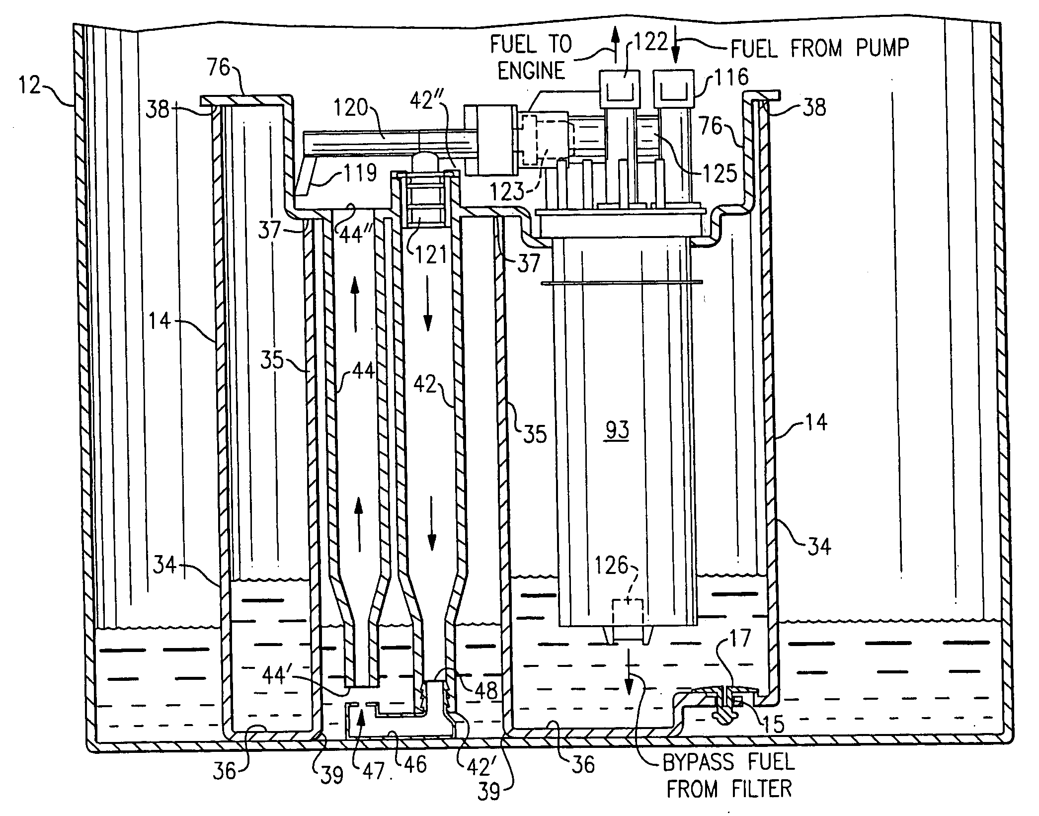
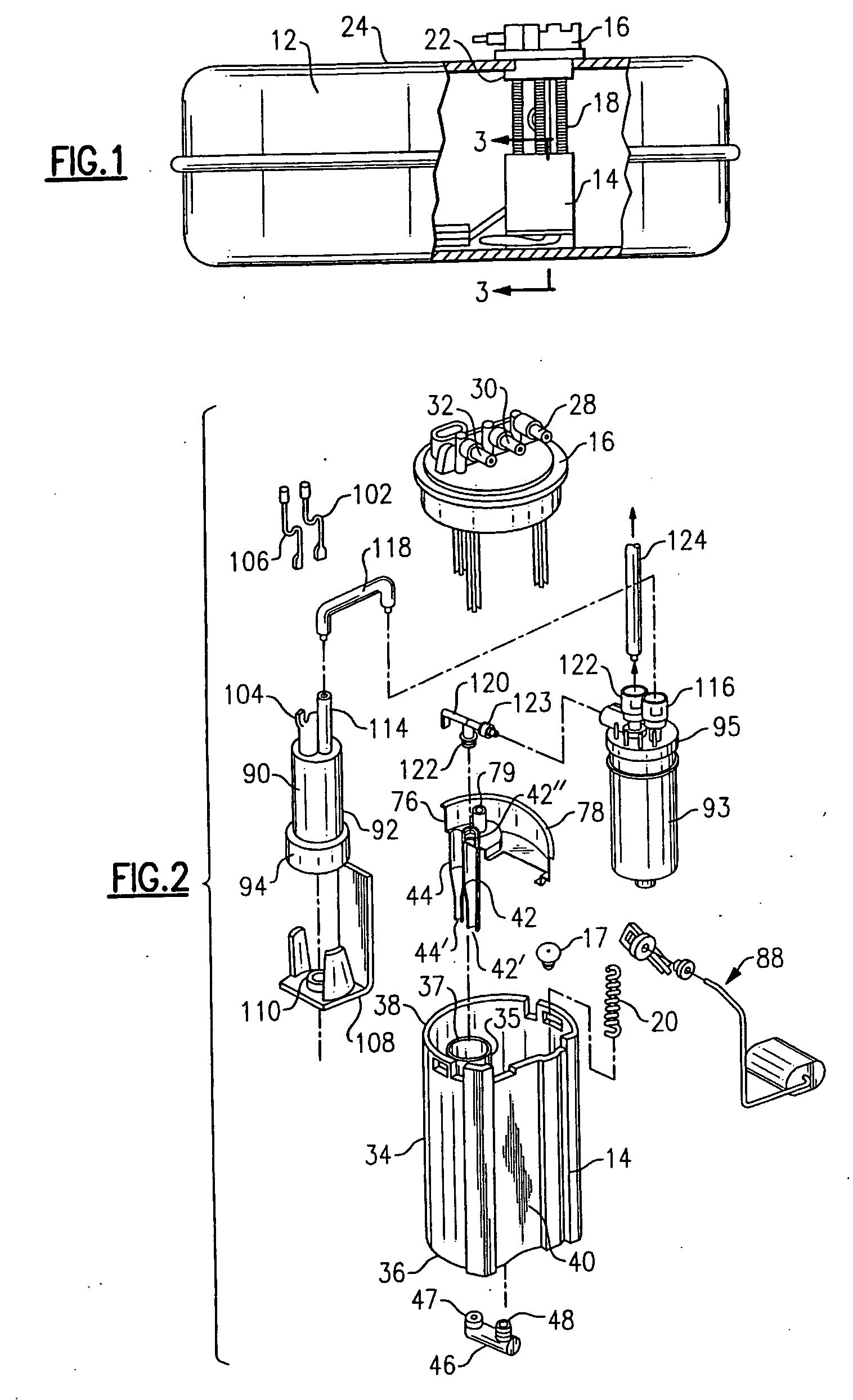
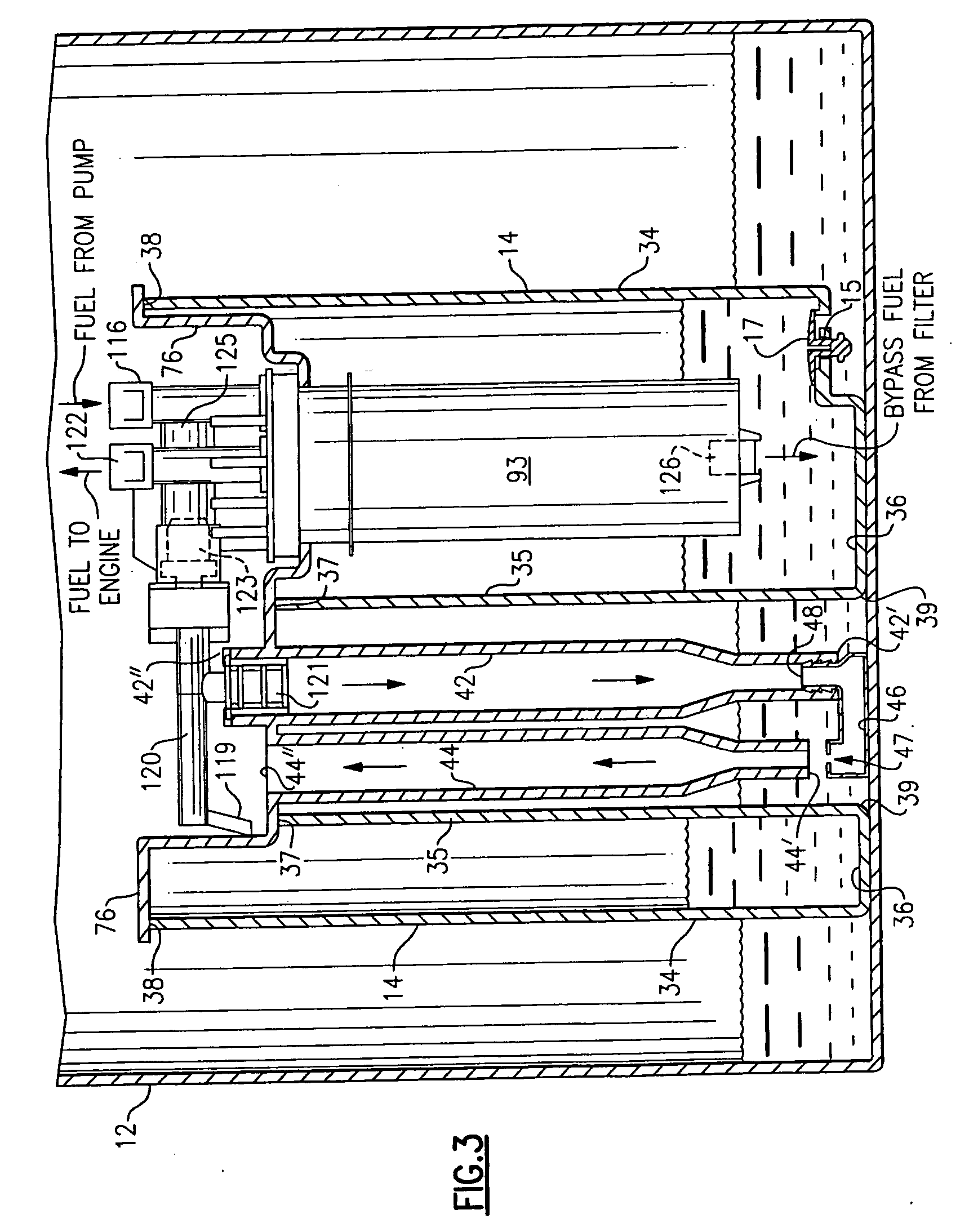
[0010] A seen best in FIGS. 1-2, a modular fuel reservoir (MFR) 10 according to this invention is disposed in a motor vehicle fuel tank 12. MFR 10 includes a reservoir 14, a tank cover 16, a plurality of vertical guide rods 18 on the tank cover slidably connected to the reservoir, and a spring 20 urging relative separation between the tank cover and the reservoir. The tank cover 16 seals closed an access port 22 in a top 24 of the fuel tank through which the MFR 10 may be inserted into the tank. The spring 20 biases the reservoir 14 against a bottom 26 of the fuel tank. A discharge fluid connector 28 and a return fluid connector 30 on the tank cover 16 are linked by external fluid conduits to the motor vehicle engine (not shown). A vapor connector 32 on the tank cover is also linked by an external conduit to a vapor storage device on the vehicle (not shown).

[0011] Reservoir 14 includes a side wall 34 and a bottom wall 36 leading inwardly to an open, vertically extending wall struct...


PUM

PropertyMeasurementUnit
Fractionaaaaaaaaaa
Electrical conductivityaaaaaaaaaa
Electrical conductoraaaaaaaaaa

Abstract

A modular fuel reservoir assembly for incorporation into a vehicle fuel tank includes a fuel reservoir, a fuel pump, a fuel filter and a retainer. The retainer is formed of an electrically conductive material and includes integrally formed and electrically conductive fuel supply and fill tubes fluidly interconnected at the open bottom ends thereof by a jet pump. The reservoir includes an internal vertical column through which the supply and fill tubes freely extend such that the jet pump is located adjacent the open bottom of the reservoir column. Fuel from the tank and bypass fuel from the reservoir travel through the fill tube and empty back into the reservoir until all fuel in the tank is depleted.

Description

TECHNICAL FIELD [0001] The invention relates to a modular fuel reservoir assembly in a motor vehicle fuel tank. BACKGROUND OF THE INVENTION [0002] Present day vehicle fuel systems may include an assembly commonly referred to as a “modular fuel reservoir” (MFR) assembly in the fuel tank of the motor vehicle. A typical MFR includes a tank cover, a cup-shaped plastic reservoir, a plurality of guide rods on the tank cover slidably connected to the reservoir, and a spring urging relative separation between the tank cover and the reservoir. The MFR is inserted into the fuel tank through an access port in the top of the fuel tank which is sealed closed by the tank cover and a rubber seal. The spring biases the reservoir against the bottom of the fuel tank. A plastic retainer on the top of the plastic reservoir locates a fuel pump and fuel filter in the reservoir. The electric motor of the fuel pump is turned on and off through a wiring harness of the motor vehicle. When the electric motor ...

Claims


Application Information

Patent Timeline
IPC IPC(8): B60K15/077
CPCB60K15/077B60K2015/03105F02M37/025F02M37/106Y10T137/86075
Inventor WITHERSPOON, CHRIS I.BEYER, SHARON E.WILLIAMS, RONALD L.JEFFERS, JAMES W.
Owner DELPHI TECH INC
Why Eureka
Try Eureka