
Surgical stapling instrument having force controlled spacing end effector

a technology of end effector and surgical stapler, which is applied in the direction of surgical staples, paper/cardboard containers, applications, etc., to achieve the effects of enhancing clinical flexibility, preventing excessive flexure, and reducing the thickness of compressed tissu

Active Publication Date:
View PDF99 Cites 236 Cited by
  • Summary
  • Abstract
  • Description
  • Claims
  • Application Information

AI Technical Summary

Benefits of technology

[0009] The invention overcomes the above-noted and other deficiencies of the prior art by providing a surgical instrument that incorporates a firing bar that translates through a staple applying assembly having a lower jaw and a pivotally attached upper jaw, engaging each to assist in maintaining the desired spacing between inner surfaces that compress tissue in between. Advantageously, the distance between the two jaws is allowed to flex apart slightly to allow for a larger thickness of compressed tissue, yet the firing bar prevents excessive flexure that would exceed the limits on the device to form staples through the compressed tissue. Thereby, enhanced clinical flexibility is achieved with the same surgical instrument being suitable for a larger range of surgical procedures or to accommodate variations in the patient population.
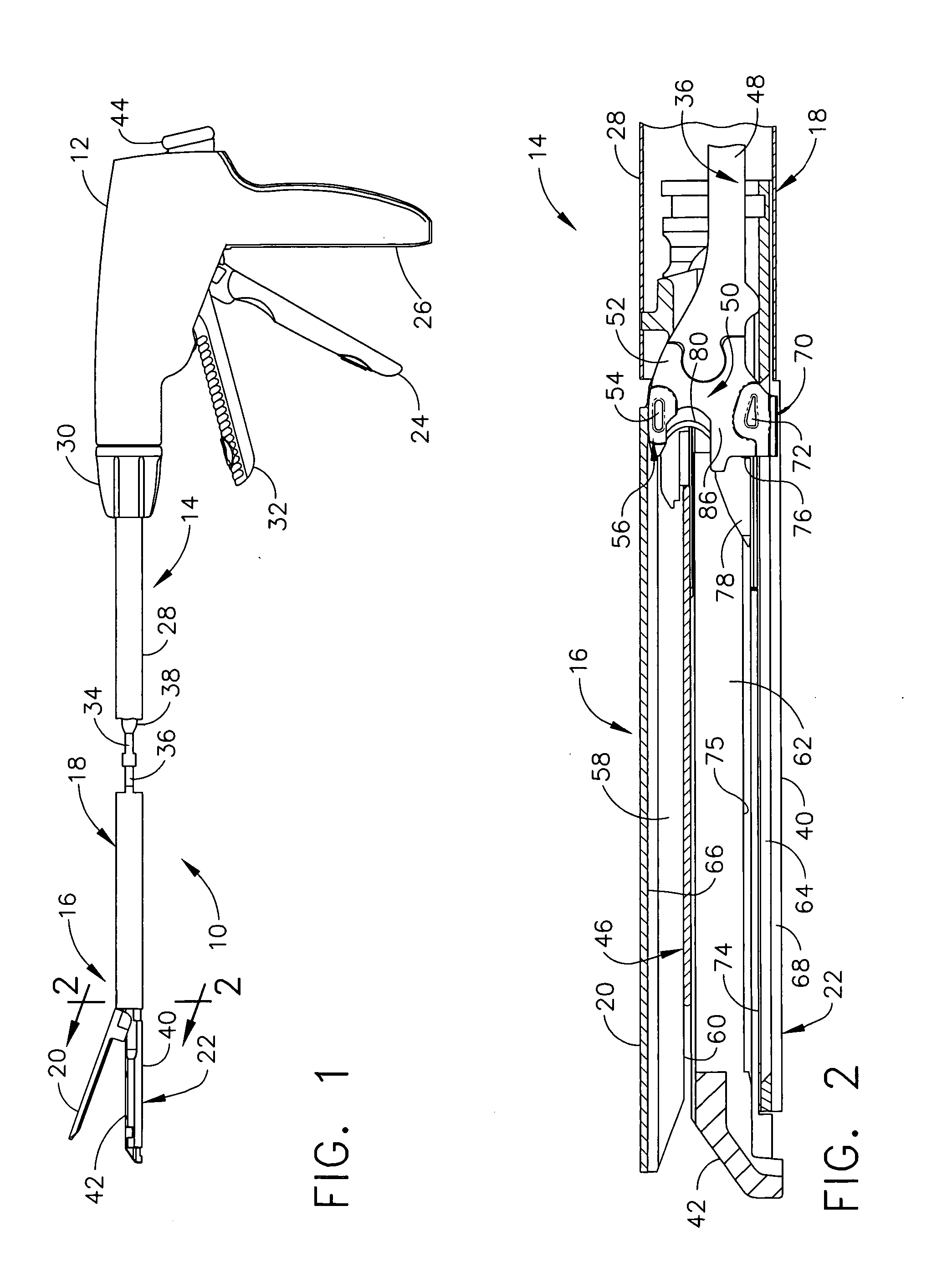
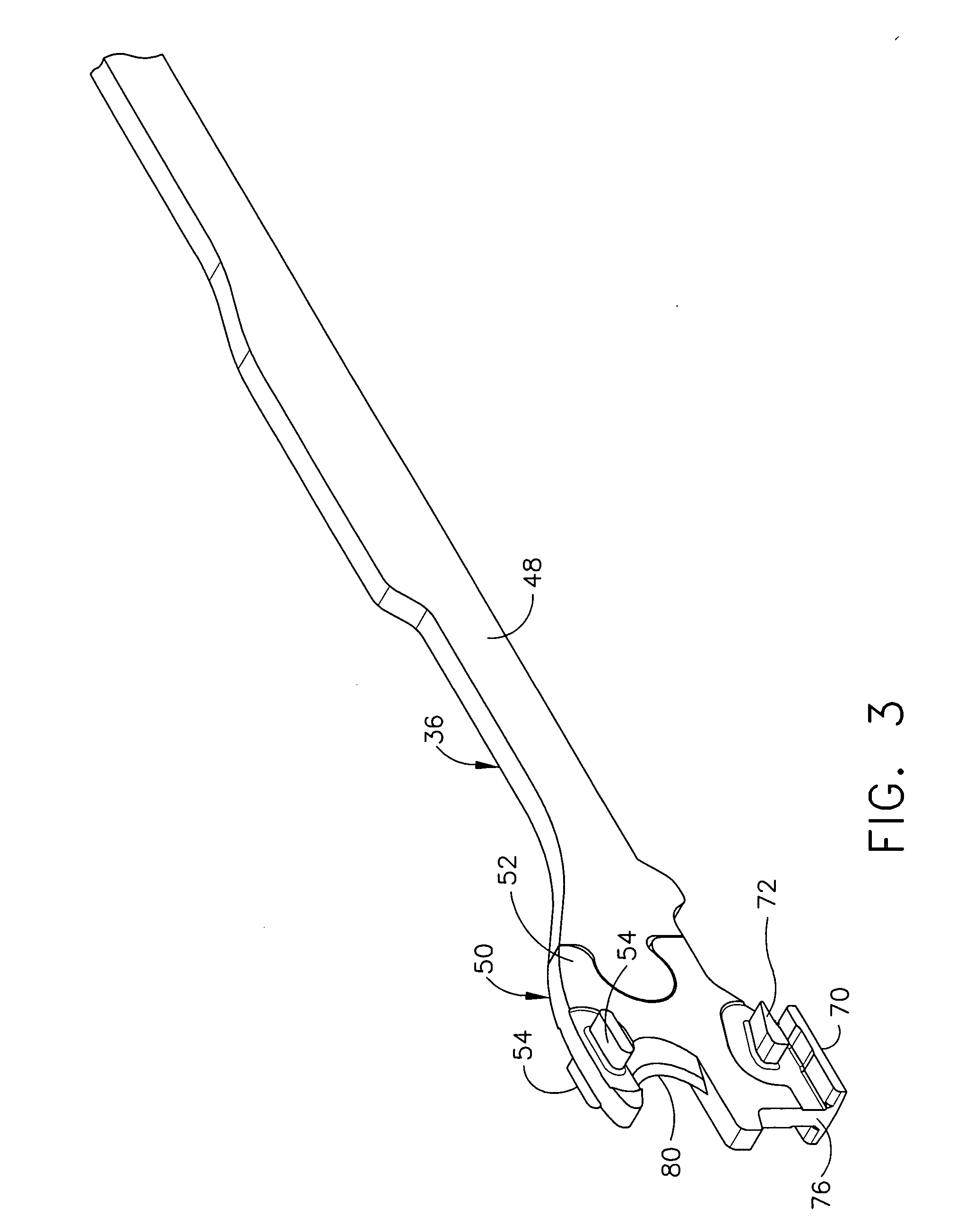
[0010] In one aspect of the invention, a surgical instrument has a lower jaw that includes an elongate staple channel having a longitudinal channel slot formed therein that receives a staple cartridge. Staples in the staple cartridge have a staple length sized for forming a closed staple between a range of tissue thicknesses. A firing bar has a vertical portion passing through a longitudinal anvil slot in an anvil pivotally attached to the elongate staple channel and passes through the longitudinal channel slot formed in the elongate staple channel. An upper lateral surface extending from the vertical portion exerts an inward compressive force on the anvil during firing translation and a lower lateral surface extending from the vertical portion exerts an inward compressive force on the elongate staple channel during firing translation. The firing bar advantageously accommodates the range of effective staple formation by including a resilient portion that varies in height between a staple forming undersurface of an anvil and an upper surface of the staple cartridge.
[0011] In another aspect of the invention, a surgical instrument has an anvil that is pivotally coupled to the elongate staple channel and includes an anvil channel that is internally formed. In particular, a vertical slot inwardly opens along a longitudinal axis of the anvil and has left and right rectangular prism-shaped recesses communicating with, bisected by, and transverse to the vertical slot, wherein said left and right rectangular prism-shaped recesses extend substantially along the longitudinal length of the vertical slot. A firing device that includes a distally presented cutting edge for severing tissue is longitudinally received between the elongate staple channel and the vertical slot of the anvil channel of the anvil. An upper member of the firing device has left and right lateral upper pins sized to slidingly engage upper and lower inner surfaces of the left and right rectangular-shaped recesses of the anvil channel. A lower member of the firing device engages the channel slot in the elongate staple cartridge. A middle member of the firing device actuates the staple cartridge by distally translating a wedge member of the staple cartridge. The firing device positively engages both the elongate staple channel and the anvil during longitudinal firing travel to provide spacing in between for staple formation. Engagement of the firing device during firing maintains vertical spacing between the elongate staple channel and the anvil resisting both pinching due to an inadequate clamped tissue and partial opening due to an excessive amount of clamped tissue. This affirmative spacing is advantageously varied within an effective range of the staple length of the staple cartridge by incorporating a resilient portion in the firing device to allow some flexure to accommodate an increased compression load due to a thicker layer of clamped tissue.

Problems solved by technology

Engagement of the firing device during firing maintains vertical spacing between the elongate staple channel and the anvil resisting both pinching due to an inadequate clamped tissue and partial opening due to an excessive amount of clamped tissue.

Method used


Image

  • Surgical stapling instrument having force controlled spacing end effector
  • Surgical stapling instrument having force controlled spacing end effector
  • Surgical stapling instrument having force controlled spacing end effector

Examples


Embodiment Construction

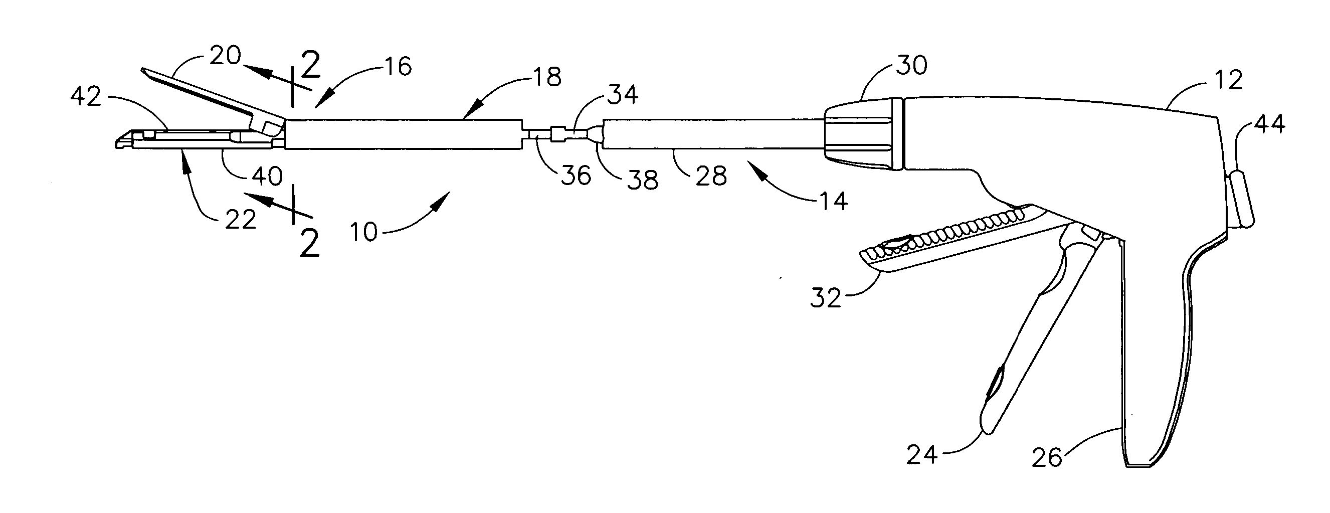
[0028] Turning to the Drawings, wherein like numerals denote like components throughout the several views, in FIG. 1, a surgical stapling and severing instrument 10 includes a handle portion 12 that is manipulated to position an implement portion 14 including a fastening end effector, depicted as a staple applying assembly 16, distally attached to an elongate shaft 18. The implement portion 14 is sized for insertion through a cannula of a trocar (not shown) for an endoscopic or laparoscopic surgical procedure with an upper jaw (anvil) 20 and a lower jaw 22 of the staple applying assembly 16 closed by depression of a closure trigger 24 toward a pistol grip 26 of the handle portion 12, which advances an outer closure sleeve 28 of the elongate shaft 18 to pivot shut the anvil 20.

[0029] Once inserted into an insufflated body cavity or lumen, the surgeon may rotate the implement portion 14 about its longitudinal axis by twisting a shaft rotation knob 30 that engages across a distal end ...


PUM

PropertyMeasurementUnit
lengthaaaaaaaaaa
heightaaaaaaaaaa
lengthaaaaaaaaaa

Abstract

A surgical instrument for being endoscopically or laparoscopically inserted into a surgical site for simultaneous stapling and severing of tissue includes force adjusted spacing between an upper jaw (anvil) and a lower jaw (staple cartridge engaged to an elongate staple channel) so that the height of staple formation corresponds to the thickness of the tissue, yet does not exceed the height range that may be accommodated by the length of the staples. In particular, resilient structures are formed into an E-beam firing bar that includes a cutting surface (knife) that severs tissue between a top pin that engages the anvil and a middle pin and lower foot that engage the lower jaw. The resilience responds to the force exerted by clamped tissue to vary the spacing.

Description

FIELD OF THE INVENTION [0001] The present invention relates in general to surgical stapler instruments that are capable of applying lines of staples to tissue while cutting the tissue between those staple lines and, more particularly, to improvements relating to stapler instruments and improvements in processes for forming various components of such stapler instruments including adding bolstering material to the severed and stapled tissue. BACKGROUND OF THE INVENTION [0002] Endoscopic and laparoscopic surgical instruments are often preferred over traditional open surgical devices since a smaller incision tends to reduce the post-operative recovery time and complications. The use of laparoscopic and endoscopic surgical procedures has been relatively popular and has provided additional incentive to develop the procedures further. In laparoscopic procedures, surgery is performed in the interior of the abdomen through a small incision. Similarly, in endoscopic procedures, surgery is per...

Claims


Application Information

Patent Timeline
Patent Type & Authority Applications(United States)
IPC IPC(8): A61B17/10
CPCA61B17/07207A61B19/30A61B2017/0725A61B2017/07278A61B2017/07285A61B2017/320052A61B90/03
Inventor SHELTON, FREDERICK E. IVMORGAN, JEROME R.
Learn More