Noncontact tag, control method therefor and noncontact ID identification system

a control method and non-contact technology, applied in the direction of breathing protection, separation processes, instruments, etc., can solve the problems of increasing associated costs, unable to avoid problems, and the same decoding circuit cannot recognize the same data, so as to reduce power consumption

Active Publication Date: 2007-04-05
FUJITSU SEMICON MEMORY SOLUTION LTD
View PDF4 Cites 30 Cited by
  • Summary
  • Abstract
  • Description
  • Claims
  • Application Information

AI Technical Summary

Benefits of technology

[0032] A purpose of the present invention is to reduce a power consumption of a noncontact tag at the time of receiving modulated data coexisting with a carrier.
[0033] Another purpose of the present invention is to provide a technique enabling an accurate demodulation of modulated data by different modulation system without ushering in an increased circuit size or power consumption, or a reduced communication distance, to a noncontact tag.
[0038] A fifth aspect of the present invention is to provide the noncontact tag according to the first aspect, wherein the carrier wave carries the information by either a 100% amplitude modulation or 10% amplitude modulation, and restrains the division clock from outputting during a period of an amplitude being modulated by the 100% amplitude modulation and during a period of an amplitude being modulated by the 10% amplitude modulation.
[0052] Also enabled is an acquisition of accurate communication information by accurately demodulating, and decoding, a modulated carrier wave in either of modulation systems, i.e., the case of a modulation system in which the clock extracted from a carrier wave is interrupted during a modulation period such as the ASK 100% modulation and the case of a modulation system in which the clock extracted from a carrier wave is not interrupted during a modulation period such as the ASK 10% modulation.

Problems solved by technology

Because of this, the same decoding circuit cannot recognize as the same data due to a clock difference.
However, the problem is that the positional relationship between a count value of the three-bit counter and the L level of the demodulation signal shifts with a modulation index if the same decoding circuit carries out an ASK 10% and ASK 100%.
Although a decoding is possible by a single modulation method, a problem cannot be avoided if signals of two modulation index coexist.
Accordingly, a double equipment of a decoding circuit and a demodulation circuit corresponding to each of different modulation index solves the problem for both cases of the decoding systems as disclosed by the patent document 1, this method, however, is not preferred because power consumption, logic size and area size of a chip increase and accordingly the associated cost increases.
Meanwhile, a patent document 2 has disclosed a technique for attempting to enable a modulation of normal data by a demodulation circuit presetting, in a counter circuit, a clock value equivalent to a pause period in which a demodulation clock stops as a result of the amplitude of a received radio wave becoming zero (0) by modulation in a demodulation circuit for demodulating ASK 100% modulation data, which also brings about a technical problem of a power consumption and size of logic because there is a necessity of adding the function of presetting a counter value to the demodulation circuit.

Method used


Image

  • Noncontact tag, control method therefor and noncontact ID identification system
  • Noncontact tag, control method therefor and noncontact ID identification system
  • Noncontact tag, control method therefor and noncontact ID identification system

Examples


Embodiment Construction

[0070] The following is a detailed description of the preferred embodiment of the present invention while referring to the accompanying drawings.

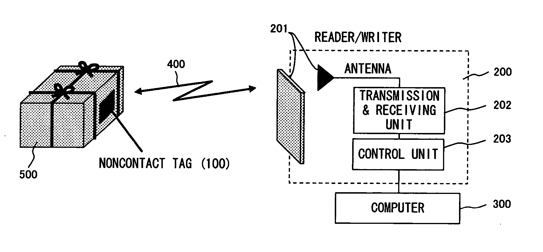
[0071]FIGS. 5, 6A and 6B are conceptual diagrams exemplifying an operation of a noncontact tag according to an embodiment of the present invention; FIG. 7 is a block diagram exemplifying a configuration of a noncontact tag according to the present embodiment; and FIGS. 8A, 8B and 8C is a block diagram exemplifying in more detail a part of configuration of a noncontact tag according to the present embodiment. And FIG. 9 is a conceptual diagram exemplifying a configuration of a noncontact ID identification system using a noncontact tag according to the present embodiment.

[0072] A noncontact ID identification system according to the present embodiment includes an on contact tag 100, a reader / writer 200 and an information processing apparatus 300.

[0073] The noncontact tag 100 is attached for example to a moving body such as a pack 500 and in...


PUM

PropertyMeasurementUnit
frequencyaaaaaaaaaa
communication distancesaaaaaaaaaa

Abstract

The present invention is to provide a noncontact tag, comprising: a clock extraction unit for extracting a clock from a received carrier wave; a demodulation unit for outputting a demodulated signal comprising a logic signal whose logic state changes responding to each of a non-modulation period and modulation period of the carrier wave; a division unit for generating a division clock from the clock input from the clock extraction unit and also restraining the division clock from being output according to a logic state of the demodulated signal; and a decoding unit for decoding information included in the carrier wave by using a value of counter driven by the division clock.

Description

CROSS-REFERENCE TO RELATED APPLICATIONS [0001] This application is based upon and claims the benefit of priority from the prior Japanese Patent Application No. 2005-289340 filed on Sep. 30, 2005, the entire contents of which are incorporated herein by reference. BACKGROUND OF THE INVENTION [0002] 1. Field of the Invention [0003] The present invention relates to a noncontact tag, control method therefor and noncontact ID identification system, and in particular to a technique effectively applicable to a passive noncontact tag which is operated by a received radio wave power, its control technique and its application system. [0004] 2. Description of the Related Art [0005] In recent years, a noncontact type ID identification system has been in the spotlight for applications, for example, to a supply chain management (SCM), logistics management, inventory management, et cetera. That is, a system for automatically identifying a subject by a reader / writer connected to a computer reading, ...

Claims


Application Information

Patent Timeline
Patent Type & Authority Applications(United States)
IPC IPC(8): G06K7/08G06K19/06
CPCG06K19/0723A62B7/10A62B9/022A62B23/02A62C13/66A62C13/76B01D46/0005
Inventor HIGASHI, NORIYUKI
Owner FUJITSU SEMICON MEMORY SOLUTION LTD
Why Eureka
Try Eureka