Devices, systems and methods for determining temperature and/or optical characteristics of a substrate

a technology of optical characteristics and devices, applied in the direction of optical radiation measurement, instruments, heat measurement, etc., can solve the problems of inability to accurately measure the true temperature of the substrate, the pyrometrically determined brightness temperature cannot be corrected to provide the true temperature, and the pyrometrically determined brightness temperature cannot be used

Inactive Publication Date: 2007-04-05
LUXTRON CORP
View PDF17 Cites 26 Cited by
  • Summary
  • Abstract
  • Description
  • Claims
  • Application Information

AI Technical Summary

Problems solved by technology

As such, a pyrometer-reflectometer instrument has not heretofore been suitable for use in connection with a deposition system that has a manifold or showerhead that may present such an obstacle.
It is often difficult to measure the true temperature of a substrate during such a deposition process using simple pyrometry, such as optical pyrometry, for a number of reasons.
As such, the emissivity applicable during the deposition process is not known, and hence, the pyrometrically determined brightness temperature cannot be corrected to provide the true temperature.
Another reason is that the presence of a manifold, a showerhead, and / or a plasma in the deposition system generally interferes with the corrective capability of the pyrometer, even when the pyrometer is a modern one of some sophistication that can measure emissivity and apply an appropriate temperature correction to such a measurement.
This interference reduces the reliability of the temperature reading obtained from such a system.
However, it is often difficult to obtain this temperature distribution using simple pyrometry, such as optical pyrometry, for various reasons.
Schemes for obtaining pyrometric measurements from the exposed front side of a substrate, such as a glass sheet, for example, are often not acceptable, as that front side becomes coated during a deposition process.
Thus, a pyrometric reading obtained from the front side of the substrate during a deposition process typically does not correspond to that for the bare, uncoated substrate, and a known, fixed temperature correction based on the emissivity of the surface of the substrate is not applicable.
Further, schemes for obtaining pyrometric measurements, such as those associated with infrared pyrometry, from the uncoated backside of the substrate during the deposition process, are not acceptable.
Unfortunately, these holes or orifices adjacent to the underside of the substrate can cause local imperfections in the finished devices that are undesirable or unacceptable.

Method used


Image

  • Devices, systems and methods for determining temperature and/or optical characteristics of a substrate
  • Devices, systems and methods for determining temperature and/or optical characteristics of a substrate
  • Devices, systems and methods for determining temperature and/or optical characteristics of a substrate

Examples


Embodiment Construction

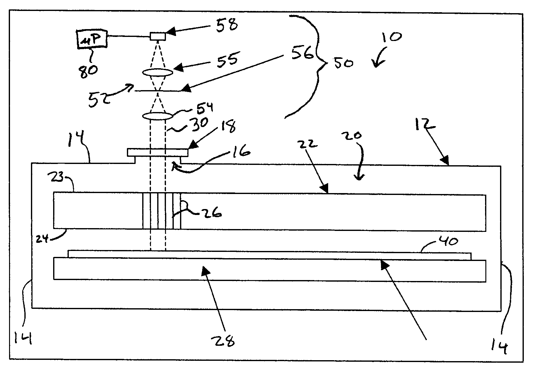
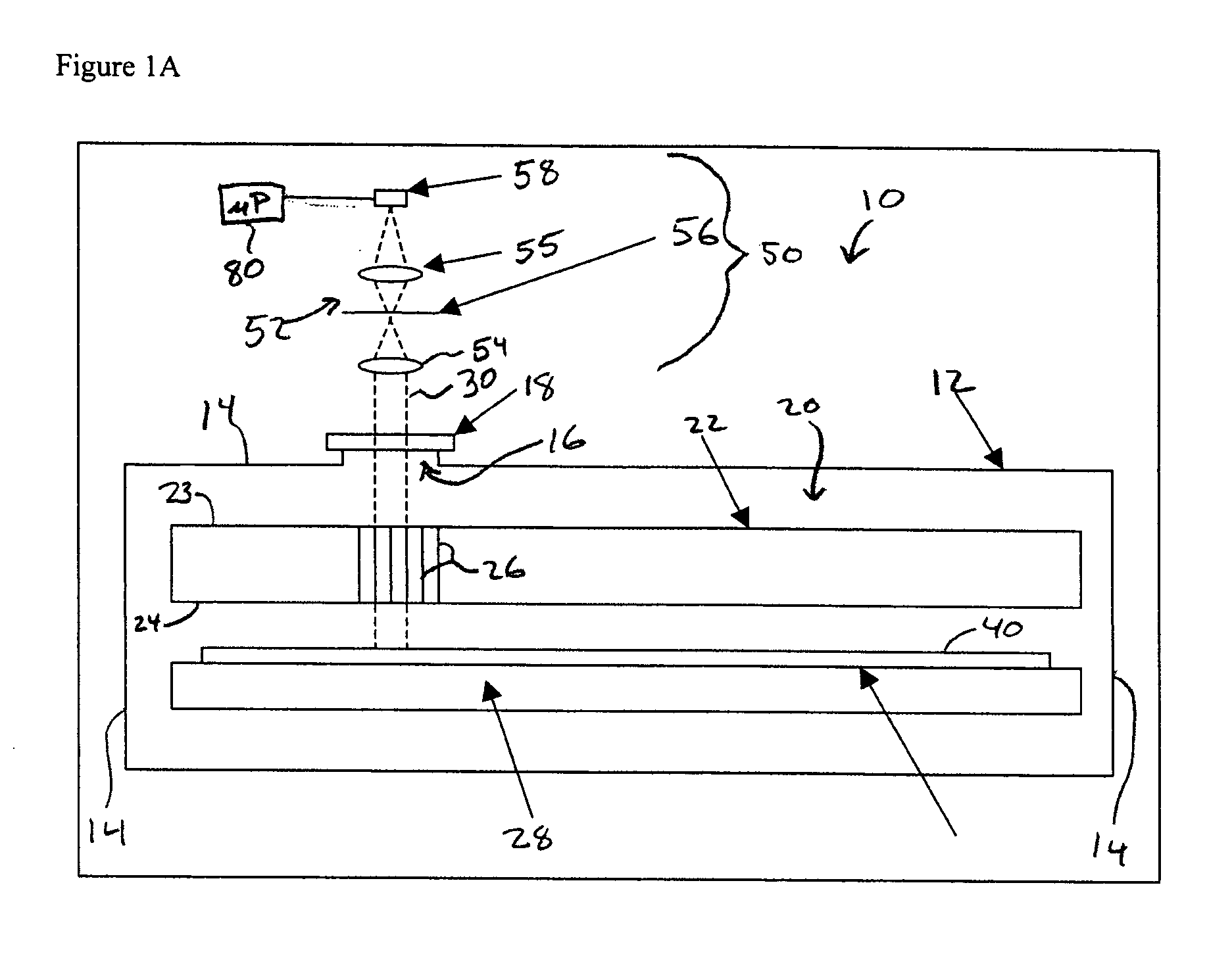
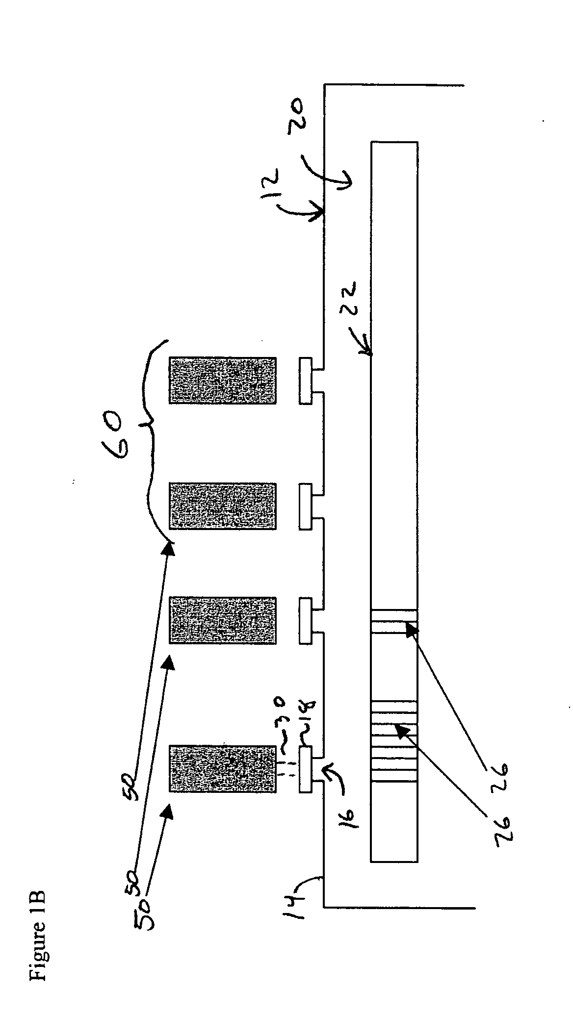
[0019] This invention is generally directed to a pyrometric device and / or system for use in determining the temperature and / or optical characteristics of a substrate. The invention is also directed to a method associated with such a device or system, for depositing or forming a material on a substrate.

[0020] In the description of the invention herein, it will be understood that a word appearing in the singular encompasses its plural counterpart, and a word appearing in the plural encompasses its singular counterpart, unless implicitly or explicitly understood or stated otherwise. Further, it will be understood that for any given component described herein, any of the possible candidates or alternatives listed for that component, may generally be used individually or in combination with one another, unless implicitly or explicitly understood or stated otherwise. Additionally, it will be understood that any list of such candidates or alternatives, is merely illustrative, not limiting...


PUM

PropertyMeasurementUnit
temperatureaaaaaaaaaa

Abstract

A system for measuring the true temperature of a substrate in a deposition system is disclosed. The temperature measurement system has at least one opening formed within a showerhead or manifold placed above a substrate of the deposition system. The temperature measurement system includes an optical pyrometer and reflectometer external to the coating chamber that looks through a window or windows and through the at least one opening in the showerhead to sense the substrate being coated. Depending on the particular chamber and showerhead configuration, the system either makes a passive emissivity correction or has an integral reflectometer for an active emissivity correction. Optical features confer an insensitivity to small motions of the showerhead in large coaters where optical alignment is not assured due to thermal and mechanical influences.

Description

CROSS-REFERENCE TO RELATED APPLICATIONS [0001] This non-provisional application is related to U.S. patent application Ser. No. 10 / 616,254 of Robert J. Champetier, entitled “Emissivity Corrected Radiation Pyrometer Integral with a Reflectometer and Roughness Sensor for Measuring True Surface Temperatures at a Distance from the Sample,” which was filed on Jul. 8, 2003, and to U.S. Provisional Application No. 60 / 397,200 of Robert J. Champetier, which was filed on Jul. 19, 2002, each of which is incorporated herein in its entirety by this reference.FIELD OF THE INVENTION [0002] This invention generally relates to devices, systems and methods of determining the temperature and / or optical characteristics of a substrate or surface, such as a substrate or surface upon which a material is deposited or a substrate or surface that undergoes any change, such as a physical or chemical change, that might alter its thermal emissivity. More particularly, this invention relates to such devices, syst...

Claims


Application Information

Patent Timeline
Patent Type & Authority Applications(United States)
IPC IPC(8): G01J5/00G01K11/00
CPCG01J5/0003G01J5/08G01J5/0806G01J5/0818G01J5/0846G01J5/0896G01J2005/0048G01K11/125G01J5/80
Inventor CHAMPETIER, ROBERT J.
Owner LUXTRON CORP
Why Eureka
Try Eureka