Speaker system with oscillation detection unit

Inactive Publication Date: 2007-04-05
ROLAND CORP
View PDF4 Cites 9 Cited by
  • Summary
  • Abstract
  • Description
  • Claims
  • Application Information

AI Technical Summary

Benefits of technology

[0029] In addition, since the air permeability is maintained around the periphery of the reflecting member (the first component part), the requirements related to the heat resistance property of the reflecting member are mitigated. Therefore, there is no need to construct the reflecting member with a metal material, which is superior in heat resistance but heavy in weight, or a functional resin that is relatively high in cost (for example, engineering plastic), and the like. It is possible to construct the reflecting member using a general use plastic resin that is relatively light in weight and low in cost. One example of such a material is ABS (acrylonitrile butadiene styrene). Accordingly, there is the advantageous result that it is possible to minimize the changes to the original oscillating action of the voice coil unit due to the use of a heavy material and to avoid the high manufacturing costs of the system from the use of high-cost materials.
[0030] In addition, since the air permeability is maintained around the periphery of the light sensor (the second component part), it is possible to prevent the occurrence of undesirable effects caused by the heat generated by the voice coil unit, such as changes to the characteristics of the light sensor unit or, in some cases, the destruction of the light sensor unit.
[0031] Furthermore, since the light sensor unit, which comprises a light emitting element and a light receiving element, can be mounted and removed from the system as a whole unit, there is the advantageous result that it is possible to improve the maintenance properties compared to the case in which the light emitting element and the light receiving element are separate units. As a single unit, the wiring length that is required for the light emitting unit and the light receiving unit can be reduced.
[0032] In accordance with the speaker system of a sixth preferred embodiment, the light emitted by the light emitting element is received directly by the light rece

Problems solved by technology

However, there are problems associated with affixing the reflecting plate to the inner surface of the dust cap, as disclosed in the first patent reference above.
These effects degrade the degree of accuracy of detecting the displacement of the oscillation system.
There are also problems in a system where, as disclosed in the second patent reference above, the reflecting plate is affixed to the lower edge portion of the voice coil unit.
One problem is that the reflecting plate causes a weight distribution imbalance of the voice coil unit with respect to a center axis of the voice coil.
With an imbalance, a rolling oscillation that involves an inclination from the center axis of the voice coil unit is produced.
Therefore, the rolling oscillation caused by the weight imbalance degrades the accuracy of the detection of the original oscillation action of the voice coil unit.
In addition, because of the rolling oscillation, ideal oscillation is not possible and sound quality becomes relatively degraded as a result.
A second proble

Method used


Image

  • Speaker system with oscillation detection unit
  • Speaker system with oscillation detection unit
  • Speaker system with oscillation detection unit

Examples


Embodiment Construction

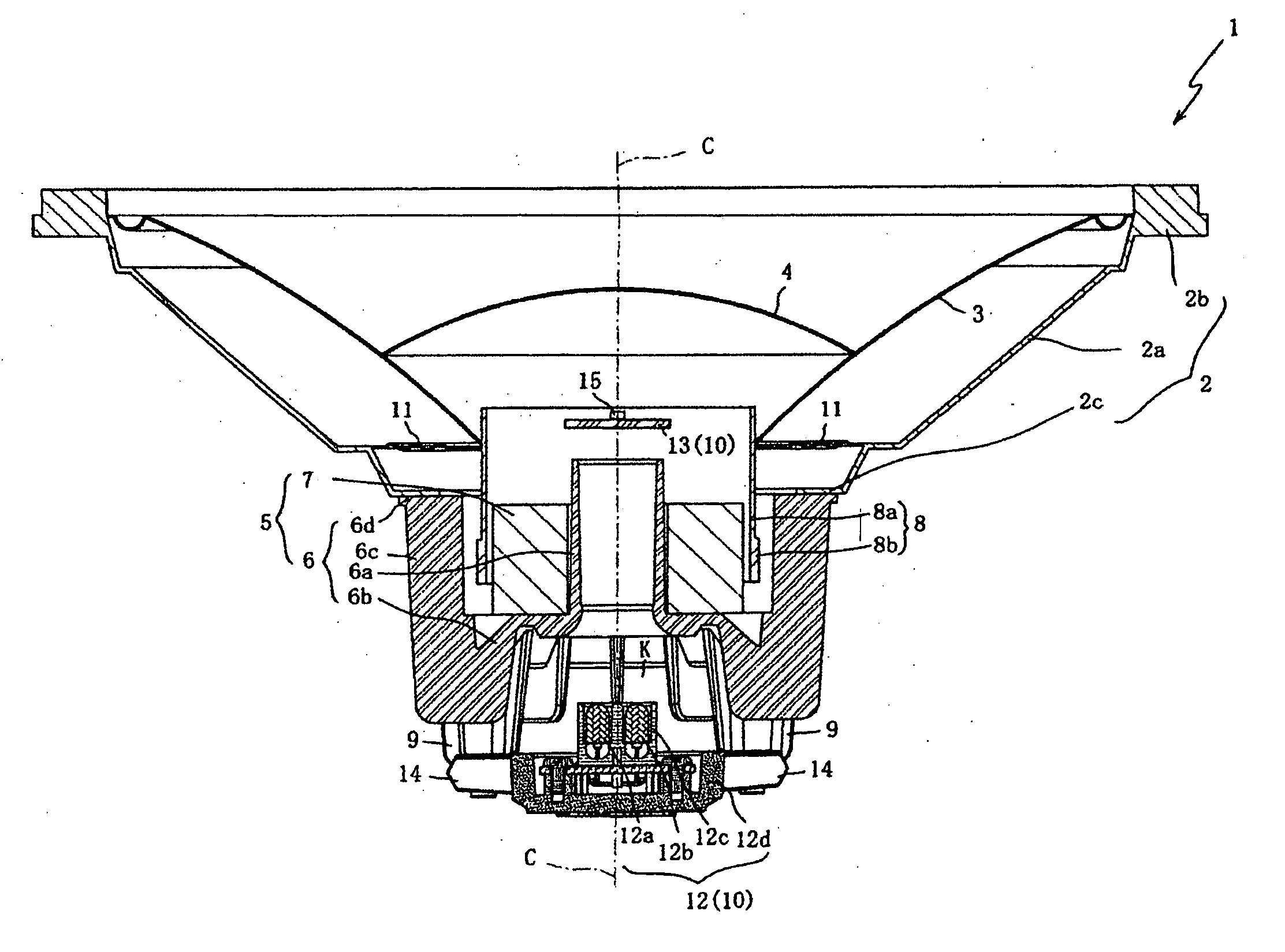
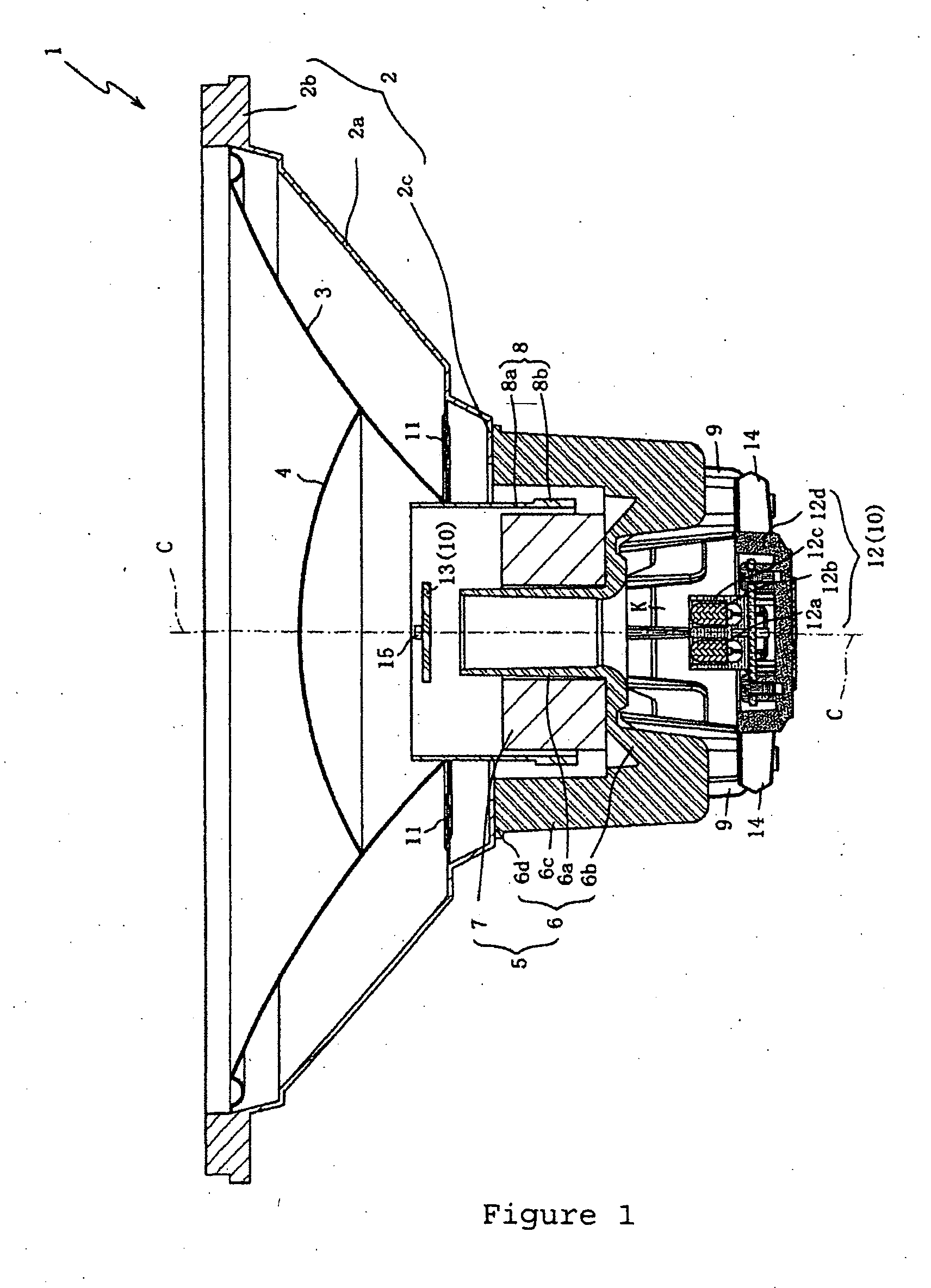
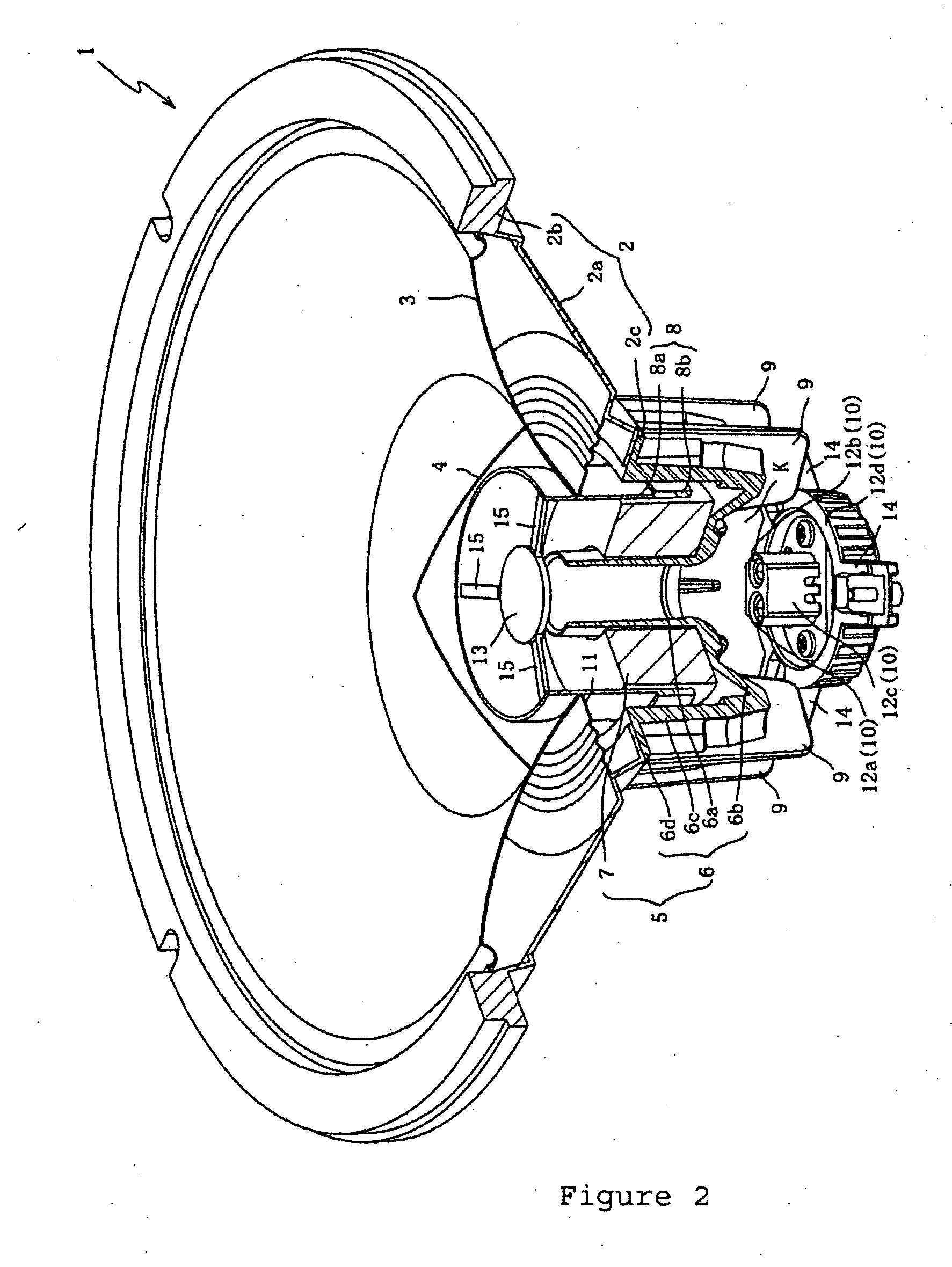
[0038] An explanation will be given below regarding preferred embodiments of the present invention while referring to the attached drawings. First, an explanation will be given regarding a first preferred embodiment of a speaker system of the present invention. FIG. 1 is a cross-section drawing of the speaker system 1 of the first preferred embodiment. FIG. 2 is an oblique external view drawing of the speaker system 1 of the first preferred embodiment and shows a portion of the speaker system 1 in cross-section.

[0039] The speaker system 1 is a system capable of detecting the oscillations of the voice coil unit 8 with a high degree of accuracy to produce a high fidelity reproduction. As is shown in FIG. 1, the speaker system 1 primarily comprises a frame 2, a cone 3, a dust cap 4, a magnetic circuit 5, a voice coil unit 8, heat radiating fins 9, and a detection unit 10.

[0040] The frame 2 supports the cone 3 and the like. The frame 2 comprises a main body frame 2a, a first flange 2b...


PUM


Abstract

A speaker system comprising a magnetic circuit, a cylindrical shaped voice coil unit generating oscillation in the magnetic circuit, an oscillating plate extending in a circular conical shape from a outer peripheral surface of the voice coil unit, a dust cap connecting to the oscillating plate covering an open face of the voice coil unit on a side surrounded by the oscillating plate, a plurality of linking members connecting to the voice coil unit, and a detection unit. The link members extend toward a center axis of the voice coil unit. The detecting unit further comprises a first component part fastened to the linking members and positioned at the center axis of the voice coil unit closer to the voice coil unit side than the dust cap, and a second component part positioned facing the first component part and is independent of the voice coil unit such that the second component part is held between the first component part and the dust cap. The detecting unit optically detects the oscillations of the voice coil unit by means of a light that courses between the previously mentioned first component part and the second component part.

Description

CROSS-REFERENCE TO RELATED PATENT APPLICATIONS [0001] The present invention relates to Japanese patent applications No. 2005-272354 (filed on Sep. 20, 2005), which was assigned to the assignees of the present invention and is incorporated herein by reference in its entirety and from which priority is claimed for the present invention. BACKGROUND OF THE INVENTION [0002] The present invention relates to a speaker system that detects the oscillation of the voice coil unit with a high degree of accuracy, thus enabling a high fidelity reproduction by the speaker system. [0003] For some time, a detection unit that detects the oscillation displacement of an oscillation system that comprises a voice coil unit, an oscillation plate, and a dust cap has been installed in speaker systems. The detection results by the detection unit are employed in generating a negative feedback through acquiring the difference between the detected oscillation displacement and the input signal. Thus, by compensa...

Claims


Application Information

Patent Timeline
IPC IPC(8): H04R9/06
CPCH04R9/02H04R9/06
Inventor TAKAGI, MASAYUKITAKATA, KOSUKEIKEGAMI, YOSHIHIRO
Owner ROLAND CORP
Why Eureka
Try Eureka