System enabling remote analysis of fluids

a technology of fluid analysis and remote analysis, applied in the field of fluid analysis, can solve the problems of difficult monitoring of fluid systems, high cost of testing time and travel, and large fluid system complexity

Inactive Publication Date: 2007-04-05
ADAMS BRUCE W +1
View PDF6 Cites 86 Cited by
  • Summary
  • Abstract
  • Description
  • Claims
  • Application Information

AI Technical Summary

Problems solved by technology

Such fluid systems are often complex and large, and the monitoring of them is a difficult task.
There is a financial cost for the time of the tester and method of travel, and with many of these sites being in remote locations, the use of vehicles or aircraft may be required.
There will often be a delay between the sampling and the results of the tests being known if the samples need to be returned to the laboratory before being tested.
Such delays can cause difficulties in alerting people to potential problems, and delays in the generation of an accurate model for the prediction of future values.
Such long intervals between tests can cause uncertainties and lack of confidence in the sample tests.
The use of a human retrieval system can have significant delay problems in such a case.
The human collection of these fluid samples has severely limited the generation of an overall model.
Limited devices are available for the remote analysis of fluids.

Method used


Image

  • System enabling remote analysis of fluids
  • System enabling remote analysis of fluids
  • System enabling remote analysis of fluids

Examples


example

Remote Device Testing Procedure

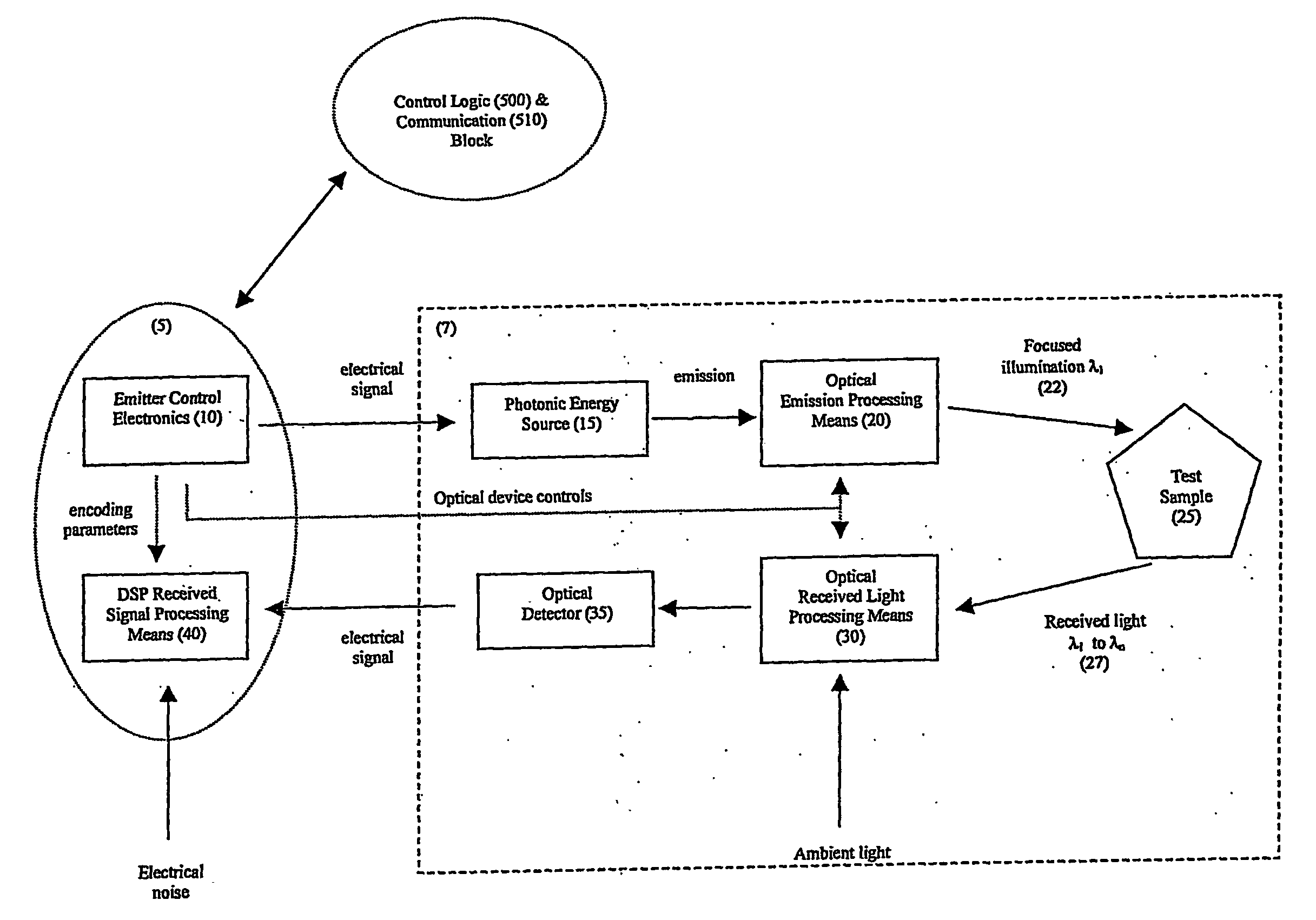
[0099] As an example, the following defines the potential optical analyses that can be performed using remote device incorporated into the fluid monitoring system according to the present invention, wherein these analyses are specific to water being the fluid being monitored. For example, the detection of turbidity in water can be based on APHA AWWA WEF physical and aggregate properties method 2130.B nephelometric and ISO. Turbidity can be a reliable method to determine the total concentration of dissolved solids in a continuous manner wherein this can be determined based on the collection of reflectance data from the water sample. In one embodiment turbidity can be measured at 590 nm and 840 nm and the illumination emitters can be high performance LED's and the optical emissions can be dispersed from the emitter lens at about 20°. The optical detector can view the emitted light path or the optical normal at a fixed angle such as 60°. For example the ...


PUM

PropertyMeasurementUnit
pressureaaaaaaaaaa
fixed angleaaaaaaaaaa
transmissionaaaaaaaaaa

Abstract

The present invention provides a system enabling the remote analysis of a fluid, wherein the analysis of the fluid and collection of data relating thereto can be provided at a plurality of remote locations by a plurality of remote devices. Each remote device is connected directly or indirectly to a central controller via one or more communication networks, thereby enabling centralised collection, evaluation and analysis of a plurality of data relating to characteristics of the fluid system being monitored. The system according to the present invention can further provide a means for the collection of strategic samples of fluid, for example, such that these samples can be collected from one or more of the remote locations at a later time for future and more detailed analysis at a laboratory or other facility. The fluid monitoring system provides a means for real time monitoring of a fluid at a plurality of locations together with a global view of the characteristics of a fluid system. In one embodiment of the invention, this fluid monitoring system can provide information and risk factors relating to real time change in the characteristics of a fluid and the fluid system.

Description

FIELD OF THE INVENTION [0001] The present invention pertains to the field of fluid analysis and in particular to a system that enables the remote analysis of fluids. BACKGROUND [0002] It is desirable that accurate sampling of fluids may be made and understood in the context of a man-made and natural fluid systems, such that an estimate of problems and potential problems may be fully understood, while allowing time and opportunity for appropriate action to be taken. The collection and analysis of fluids represents a method of evaluating the ever-changing natural and constructed environment, and has proven to be a useful way of understanding these systems. The types of fluids presently collected include, for example, fresh water, salt water, wastewater and air from the vicinity of industrial plants, coal fired hydro-electric plants, water purification plants, drinking water facilities and a variety of other areas as would be readily understood. These fluids can be tested for character...

Claims


Application Information

Patent Timeline
Patent Type & Authority Applications(United States)
IPC IPC(8): G06F19/00G01N1/10G01N1/26G01N35/00
CPCG01N1/10G01N1/26G01N21/31G01N21/64G01N35/00871G01N2035/00881
Inventor ADAMS, BRUCE W.MCCONNELL, PETER R.H.
Owner ADAMS BRUCE W
Why Eureka
Try Eureka