Secondary air supply system for internal combustion engine

Inactive Publication Date: 2007-04-12
MACALUSO ANTHONY
View PDF18 Cites 14 Cited by
  • Summary
  • Abstract
  • Description
  • Claims
  • Application Information

AI Technical Summary

Benefits of technology

[0012] The present invention provides the advantages of simplicity and cost effectiveness. An auxiliary pump is not necessary to increase the pressure of the air that is fed to the exhaust port. The system is also small and easy to arrange in position since it is

Problems solved by technology

Such systems are bulky and costly and may not adequately provide a pressure differential to suppl

Method used


Image

  • Secondary air supply system for internal combustion engine
  • Secondary air supply system for internal combustion engine
  • Secondary air supply system for internal combustion engine

Examples


Embodiment Construction

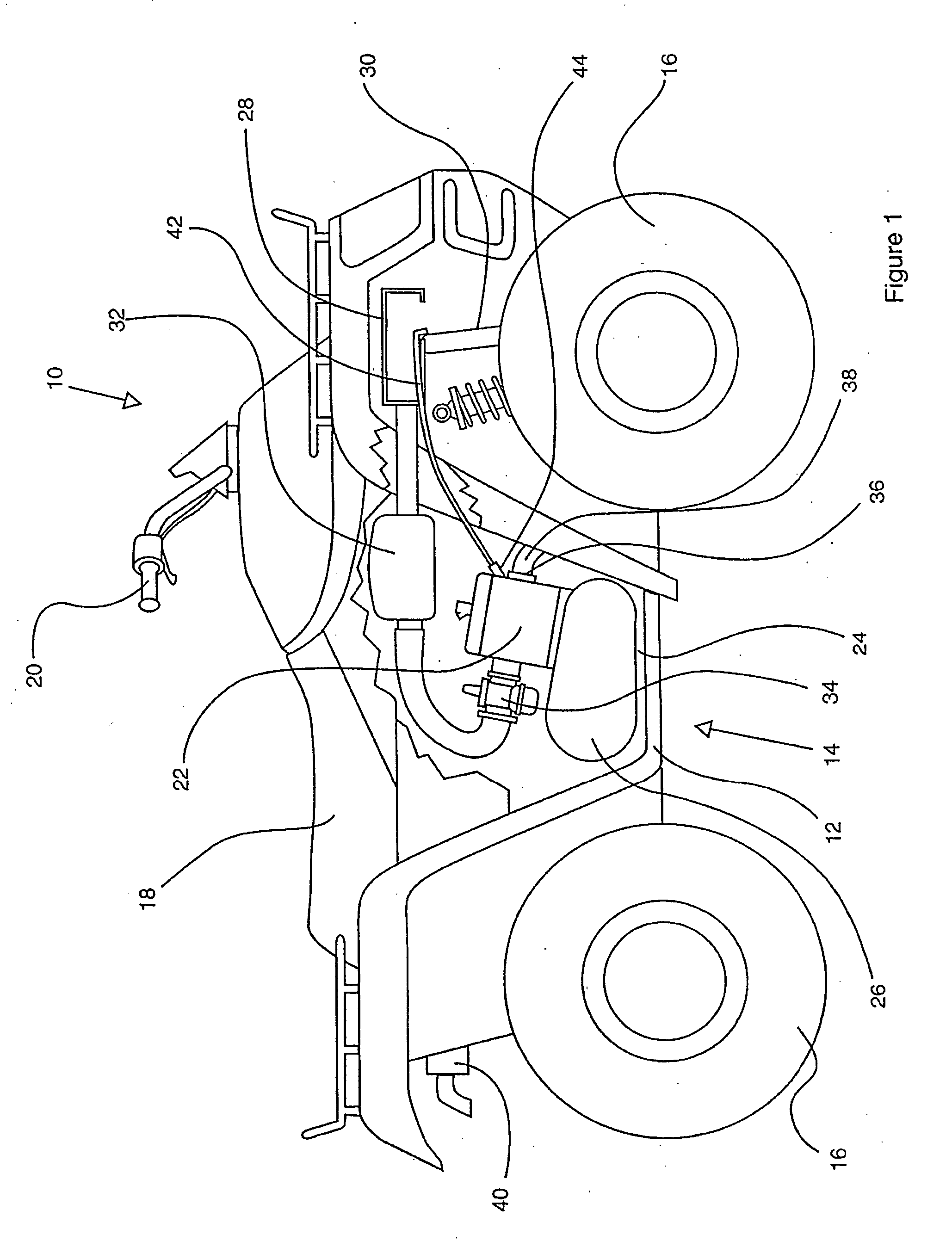
[0019] The present invention is ideally suited for motor vehicles such as all-terrain vehicles (ATVs) as illustrated in FIG. 1 with ATV 10. The invention, however, may be used with any internal combustion engine where cleaner emissions are desired.

[0020] All-terrain vehicle 10 includes a frame 12 holding an engine 14, wheels 16, seat 18, and handlebars 20. A conventional ATV arrangement is thus provided and used as an example herein of how the present invention may be situated for use in a vehicle application.

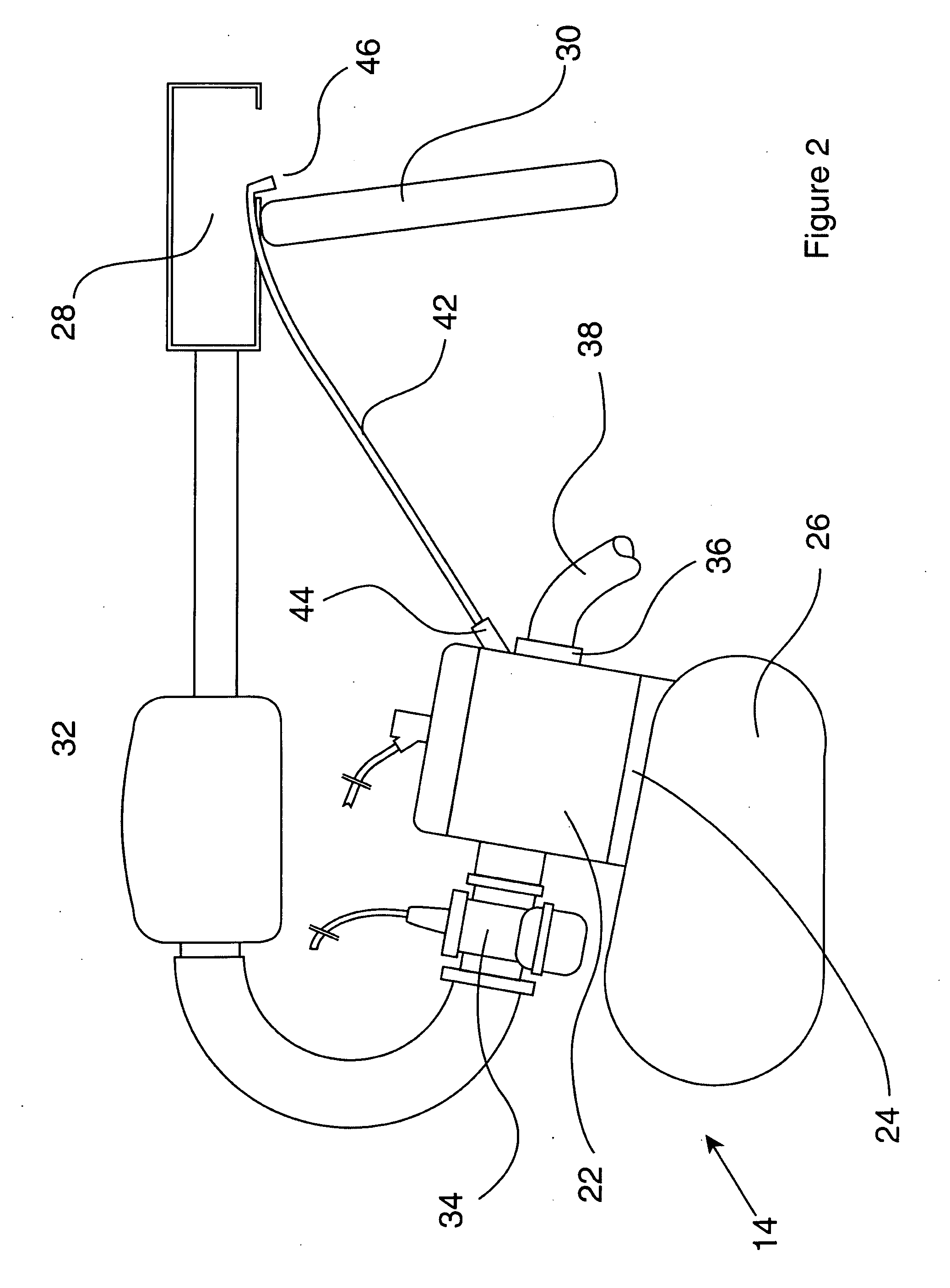
[0021] Engine 14 includes at least one cylinder 22, a crankcase 24, and a clutch compartment 26. Cylinder 22 is generally positioned atop crankcase 24. However, in alternate embodiments, multiple cylinders may be employed in various arrangements with crankcase 24.

[0022] The air intake system of engine 14 as shown in FIGS. 1 and 2 includes an air intake plenum 28 at the forward end of the vehicle. Plenum 28 includes an air inlet in front of a radiator 30. The air inlet of ple...


PUM


Abstract

The present specification discloses a system for providing a secondary air supply to an internal combustion engine so as to reduce undesirable exhaust gases. The system includes a hose running from a region of higher pressure to the exhaust port of the engine so as to supply air to such port. The area of higher pressure preferably comes from either a forward portion of the vehicle or from a high pressure region within the clutch compartment of the engine. A one-way valve is provided adjacent the exhaust port to eliminate any back flow. The method of providing secondary air supply is also disclosed.

Description

FIELD OF THE INVENTION [0001] This invention relates generally to emission control systems for internal combustion engines and, more specifically, to a secondary air supply system for an engine. BACKGROUND OF THE INVENTION [0002] Systems have been developed to supply additional air to the hot exhaust gases of an internal combustion engine in order to reduce carbon monoxide and hydrocarbon emissions. Systems, such as that described in U.S. Pat. No. 6,382,197 to Matsumoto, employ a secondary air valve apparatus that pulls air from the air cleaner. The air is fed to the exhaust port—drawn by negative pressure created at the port when the combustion-chamber exhaust valves are closed. The additional air combined with the high temperatures present at the exhaust port helps complete combustion of unburned hydrocarbons and reacts with the carbon monoxide present to produce carbon dioxide. [0003] The exhaust gases are emitted in pulses, controlled by the exhaust valves as spent fuel from a c...

Claims


Application Information

Patent Timeline
IPC IPC(8): F01N3/00F01N3/10F01N5/04
CPCF01N3/30F01N2270/04Y02T10/20Y02T10/12Y02A50/20
Inventor MACALUSO, ANTHONY
Owner MACALUSO ANTHONY
Why Eureka
Try Eureka