
Combustion engine

Active Publication Date: 2013-01-24
EXODUS R&D INT PTE
View PDF11 Cites 6 Cited by
  • Summary
  • Abstract
  • Description
  • Claims
  • Application Information

AI Technical Summary

Benefits of technology

The patent describes a new design for a mechanism used in a power tool. The design allows for a longer period of time for the piston to be in a topmost position, which leads to more efficient fuel combustion and a higher torque power output. This also reduces emissions and increases reliability. The mechanism is controlled by a wheel member that can be switched between a crank and a cam position, allowing for the piston and crank shaft to be decoupled and giving the piston more time to combust the fuel effectively.

Problems solved by technology

Nonetheless, time has proven that these types of internal combustion engines do have significant disadvantages and limitations.
The use of convention scotch yokes is not always possible for the most part as the piston stroke is short and the time available for drawing air into the combustion chamber is very short.
This causes combustion at less than the ideal 15 to 1 air / fuel ration for the fuel which in turn, leaves unburnt fuel to be exhausted as pollutants into the atmosphere.
With the exhausted unburnt fuel goes wasted energy which should have been converted to power to drive the piston.
What effectively is happening in both currently available slider crank engines as well as Scotch yoke base designs is that there is inefficient coupling between the piston rod and the crank shaft, and to date, to overcome this problem all people have ever done is to try to counteract the problem by including additional expensive intake valves placed into each cylinder to facilitate the additional air intake that has resulted from incomplete combustion of the air / fuel mixture.

Method used


Image

  • Combustion engine
  • Combustion engine
  • Combustion engine

Examples


Embodiment Construction

[0049]The following detailed description of the invention refers to the accompanying drawings. Although the description includes exemplary embodiments, other embodiments are possible, and changes may be made to the embodiments described without departing from the spirit and scope of the invention. Wherever possible, the same reference numbers will be used throughout the embodiments and the following description to refer to the same and like parts.

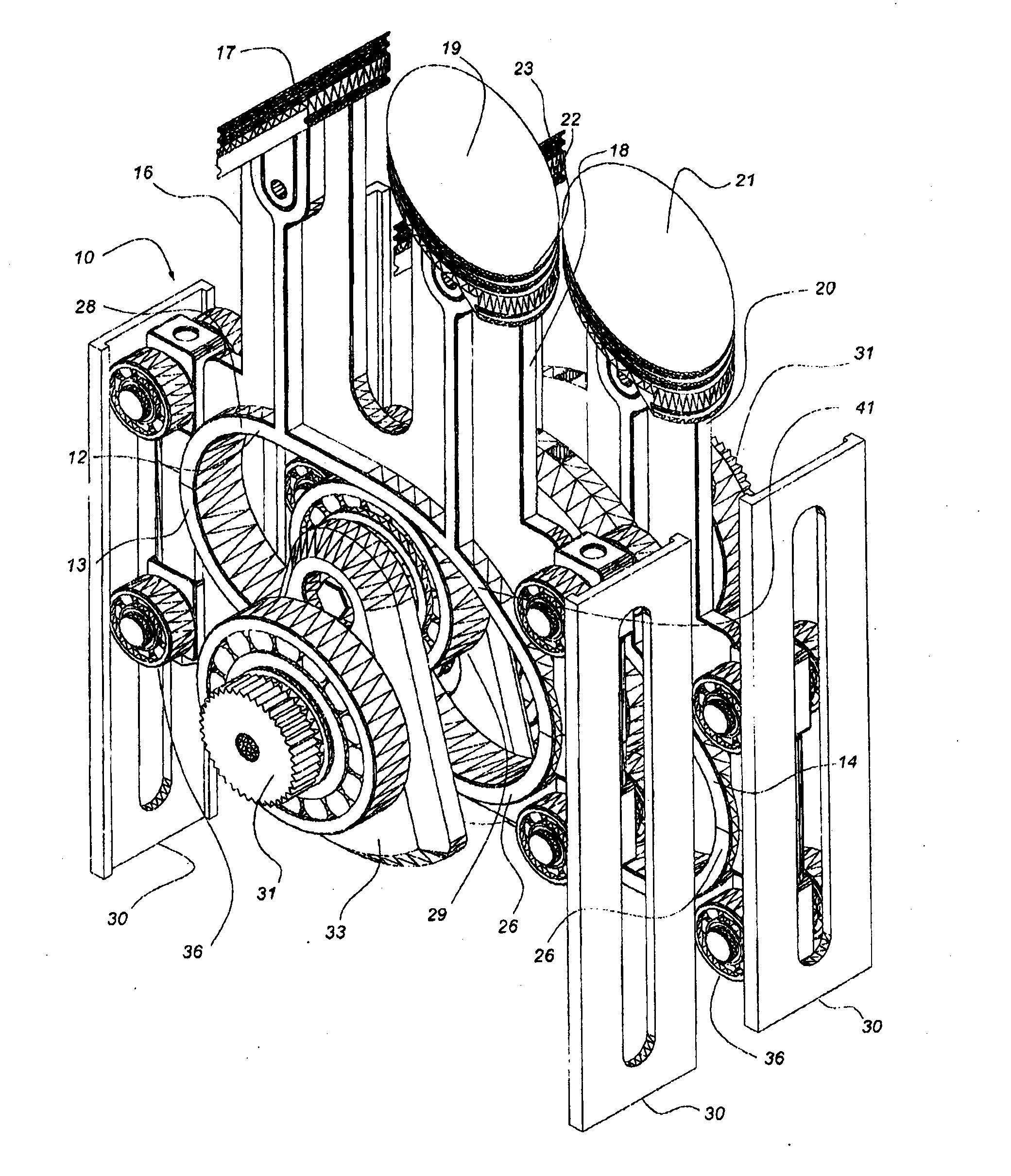
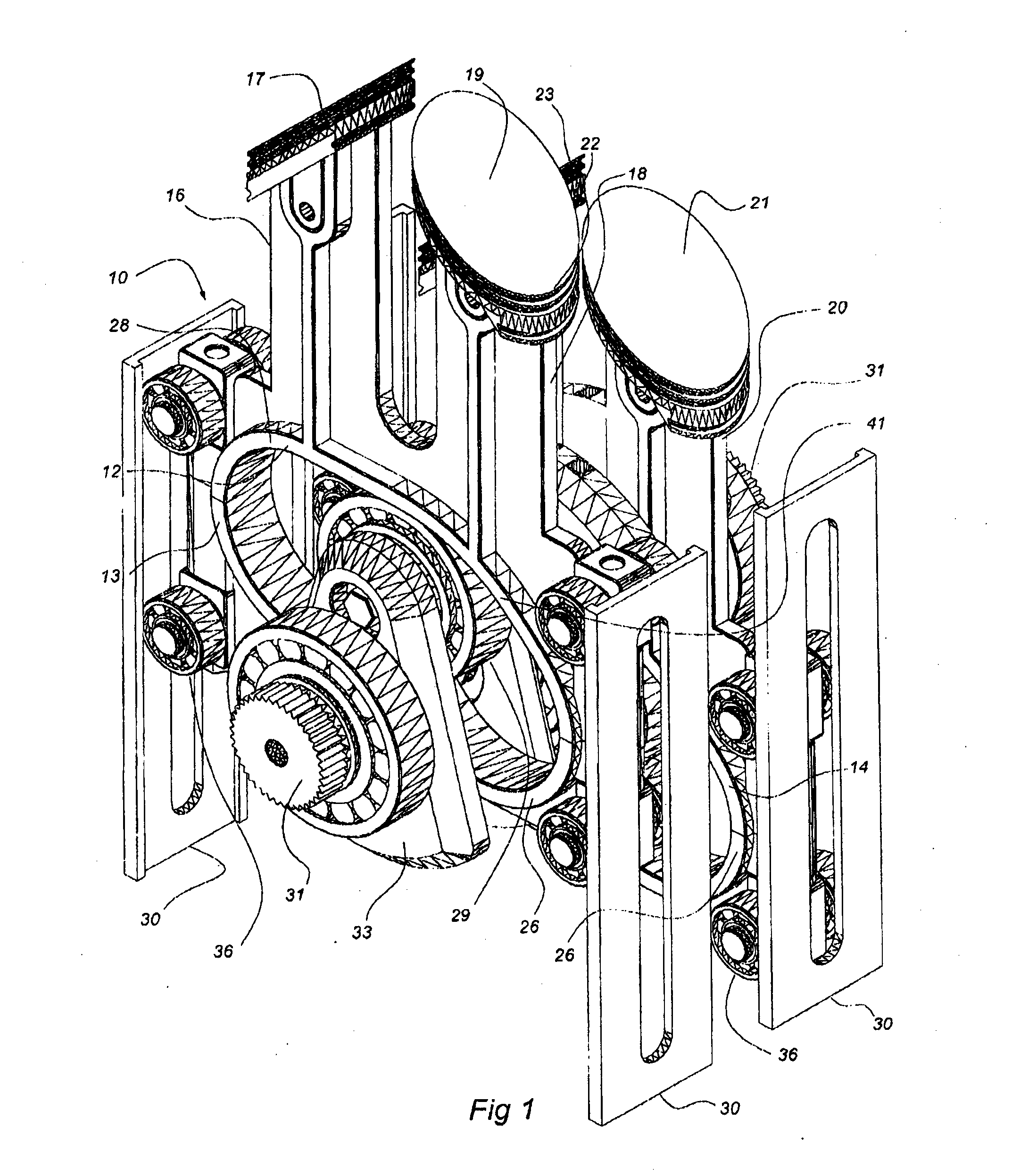
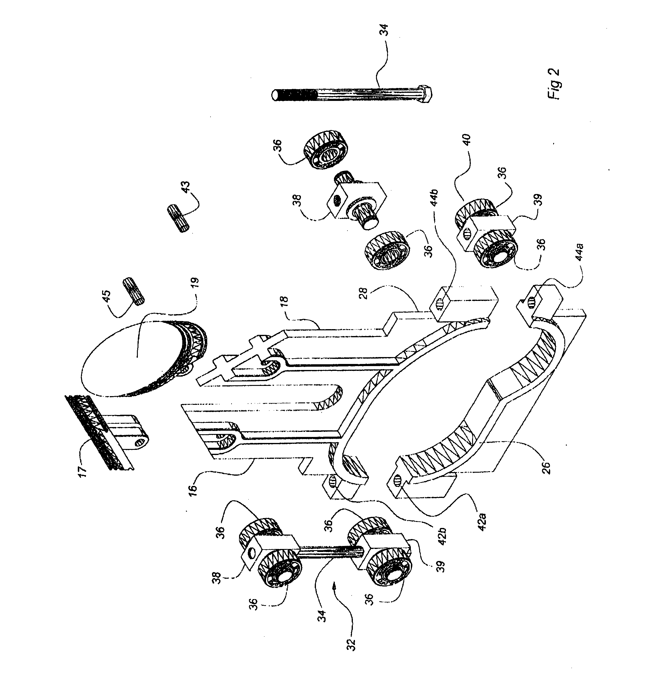
[0050]Referring to the drawings now in greater detail, wherein the internal combustion engine 10 would include as part of its arrangement a Scotch yoke structure 12 which is divided into top portion 28 and a bottom portion 26.

[0051]The Scotch yoke structure 12 includes an inner peripheral edge 13 which provides a guide to which the wheel member 29 is adapted to rotate thereabouts.

[0052]In FIG. 1 a four piston, or more precisely, four cylinder internal combustion engine is illustrated.

[0053]For simplicity, the actual cylinder chambers to whi...


PUM


Abstract

The present invention relates to internal combustion engines and more particularly reciprocating piston engines utilising Scotch yokes to translate rectilinear movement to rotary motion. In particular, the piston and / or pistons of the engine of the present invention can be placed in their topmost position for a period of time for the effective ignition and combustion of the air / fuel mixture for a given fuel charge, hence therefore providing an increased efficiency of the piston engine with a more efficient coupling between the piston and / or the power shaft driving the crank.

Description

FIELD OF THE INVENTION[0001]This invention relates to internal combustion engines and more particularly reciprocating piston engines utilising Scotch yokes to translate rectilinear movement to rotary motion.BACKGROUND OF THE INVENTION[0002]As the person skilled in the art will appreciate, the internal combustion engine has now been with us for many decades and has become a most familiar design wherein the reciprocating piston uses connecting rods to connect the piston to the crank pins of the crank shaft to translate linear reciprocating motion of the pistons to rotary motion of the crank shaft.[0003]For the most part, a connecting rod is articulable at both ends where it attaches to the piston and crank pin. This piston is connected to the connecting rod by a wrist pin that passes through the piston and the connecting rod. For the most part, these kinds of designs for such internal combustion engines are known as slider crank engines. Nonetheless, time has proven that these types o...

Claims


Application Information

Patent Timeline
IPC IPC(8): F02B75/32
CPCF01B9/023
Inventor FLENCHE, GEORGE
Owner EXODUS R&D INT PTE
Learn More