Internal combustion engine piston with chamber

Active Publication Date: 2019-03-28
SINGH SOMENDER
View PDF2 Cites 1 Cited by
  • Summary
  • Abstract
  • Description
  • Claims
  • Application Information

AI Technical Summary

Benefits of technology

[0009]The present invention provides a piston and combustion chamber including piston crown grooves extending from the combustion bowl, promoting swirl and mix within the compressed gases locked in the bowl into an ideal mix with the introduced fuel forming into an ideal charge trapped in the bowl of t

Problems solved by technology

Once compression starts to buildup in a diminishing cylinder, the induced swirl loses momentum nearing TDC due to density increases determined by the compression ratio leading to stagnation.
However, once the cylinder starts to diminish due to piston movements a proportionate increase in heat occurs within the trapped charge due to rapid increases in density further dropping the induced turbulence resulting in harsh unpredictable combustion in clusters of oxygen/hydrocarbon rich pockets to produce rapid pressure increases in the form of thermal expansions in the hot gases during the combustion process in all types of air breathing I.C. Engines.
The oxygen in the air is the primary oxidant to oxidize hydrocarbon fuels to initiate a chemical/thermal reaction resulting in combustion, unleashing extreme heat leading to rapid thermal expansions in the trapped nitrogen.
Most often erratic uncontrolled combustion takes place in pockets of sensitive heat trapped areas due to improper mixing, lacking homogeneity in the charge forming into emissions of UHC, CO, soot and NOx reflecting poor thermal efficiency out of I.C. Engines.
Frequently, in-cylinder combustion is unpredictable due to

Method used


Image

  • Internal combustion engine piston with chamber
  • Internal combustion engine piston with chamber

Examples


Example

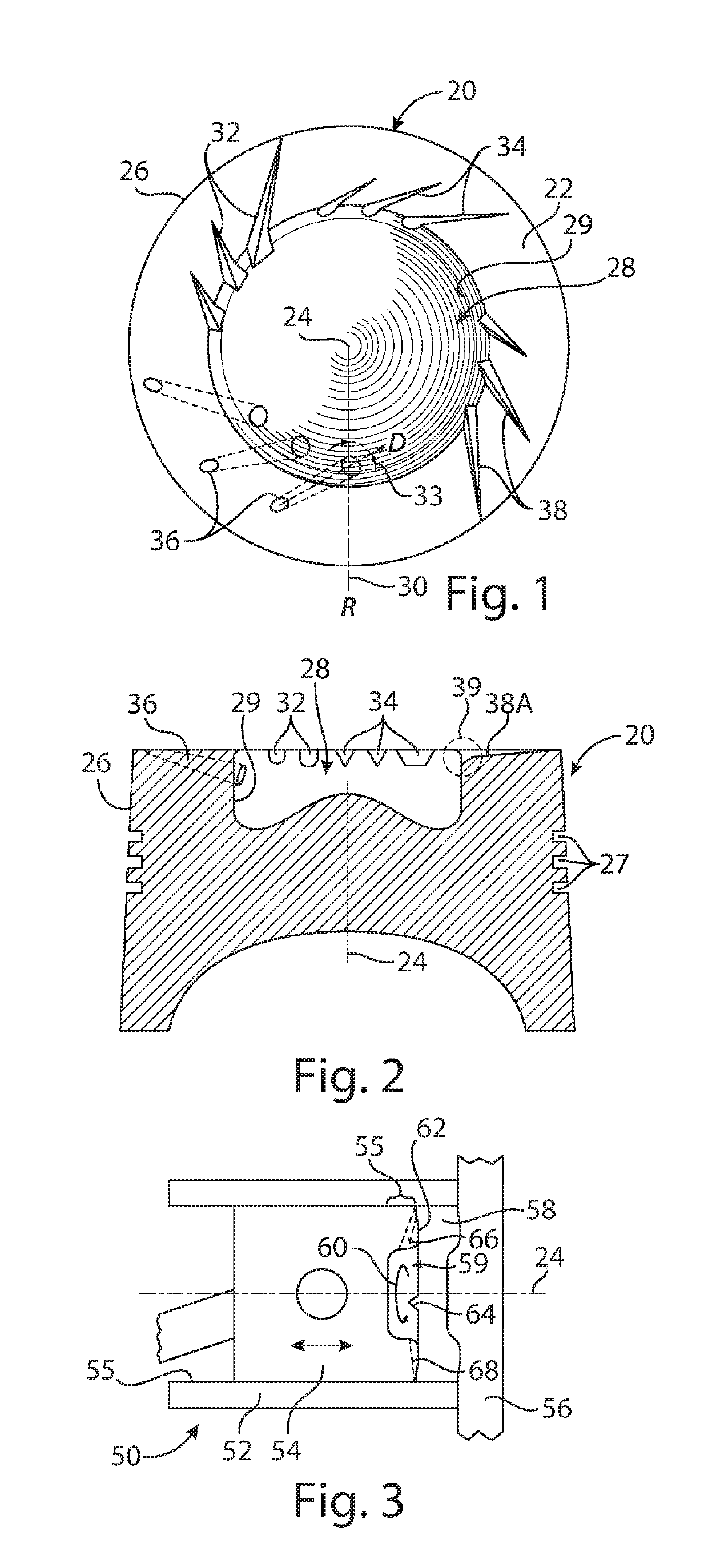
[0027]In and part of the top surface 22 of a piston 20 crown shown in FIG. 1 are three different representative forms of grooves 32, 34 and passages 36 that extend generally radially outward from the piston bowl 28 center 24 toward, and in some embodiments, to the outer periphery 26 of the piston crown. The grooves 32, 34 and passages 36 typically have an inner end at the wall 29 of a combustion bowl 28 formed as a recessed area extending from and away from the piston top surface 22. Moreover, the grooves 32, 34 and passages may be curved or straight, and may have a direction D offset from a radial line R, 30 by an angle 33 wherein the direction is between the bowl center 24 and the bowl wall 29 to encourage the formation of a swirl motion (60, FIG. 3) of combustion mixture therein. The grooves 32, 34, 36 are shown together in a single, exemplary embodiment to illustrate that more than one type of grooves and / or passages can be provided in an embodiment; however, embodiments having ...


PUM


Abstract

A piston and combustion chamber including piston crown grooves extending from the combustion bowl, promoting swirl and mix within the compressed atmospheric air/gases made up of 78% nitrogen along with 20% oxygen locked in the bowl into an ideal mix with the introduced fuel forming into an ideal charge trapped in the bowl of the piston crown improve thermal efficiencies by overcoming erratic, incomplete and improper combustion resulting in lower emissions that can prevent environmental damages due to pollution from UHC, CO, NOx, soot with the least carbon dioxide formations when using carbon rich fuels such as diesel engine operations under full load.

Description

FIELD OF THE INVENTION[0001]The present invention relates to internal combustion engines, in particular, to internal combustion engine pistons and combustion chambers.BACKGROUND OF INVENTION[0002]Turbulence and swirl are both very important factors to achieve proper mixture formations in a compressing charge to extract maximum thermal energy out of optimum thermal expansions from laminar combustion in I.C. Engines. Induced Turbulence with the help of swirl ports with various twists and hurdles only lasts till the inlet valve shuts. Once compression starts to buildup in a diminishing cylinder, the induced swirl loses momentum nearing TDC due to density increases determined by the compression ratio leading to stagnation. Any form of turbulence at this stage is generated out of squishing the mixture in the desired directions by mirroring the outer rim of the piston crown with the cylinder head forming the combustion chamber. Turbo and Super Chargers achieve force filling of cylinders t...

Claims


Application Information

Patent Timeline
IPC IPC(8): F02F3/24F02F3/26
CPCF02F3/24F02F3/26F02B23/06F02B23/0627Y02T10/12
Inventor SINGH, SOMENDER
Owner SINGH SOMENDER
Why Eureka
Try Eureka