Piston engine

a technology of piston engine and piston rod, which is applied in the direction of bearings, engine lubrication, connecting rods, etc., can solve the problems of relatively voluminous and complex cross-head piston engin

Inactive Publication Date: 2007-04-12
NEANDER MOTORS
View PDF1 Cites 15 Cited by
  • Summary
  • Abstract
  • Description
  • Claims
  • Application Information

AI Technical Summary

Benefits of technology

[0005] It is therefore an object of the present invention to provide a piston engine with at least one dry-running piston-cylinder unit which is compact in construction and which assures that the piston runs dry in the cylinder even under demanding operating conditions.
[0006] A dual crankshafts piston engine according to the present invention employs two crankshafts which rotate synchronously in opposite directions. Each crankshaft is connected to the piston via a piston rod. As a result, the piston is not subject to tipping forces, so that it can be reliably guided inside the cylinder. This eliminates the need of prior art crosshead-piston engines for additional guidance by way of a second piston section in the lower portion of the cylinder. The crankshafts of the piston engine of the present invention are journalled in a separate housing that contains a lubricant, and end portions of the crankshafts sealingly project therefrom. As a result, the crank gear associated with the piston-cylinder unit can be arranged outside the housing that contains the lubricant, thereby eliminating the danger that lubricant enters the compression space of the piston-cylinder unit.

Problems solved by technology

Such a crosshead-piston engine is relatively voluminous and complex due to the two-part piston and the associated, relatively long cylinder required thereby.

Method used


Image

  • Piston engine
  • Piston engine
  • Piston engine

Examples


Embodiment Construction

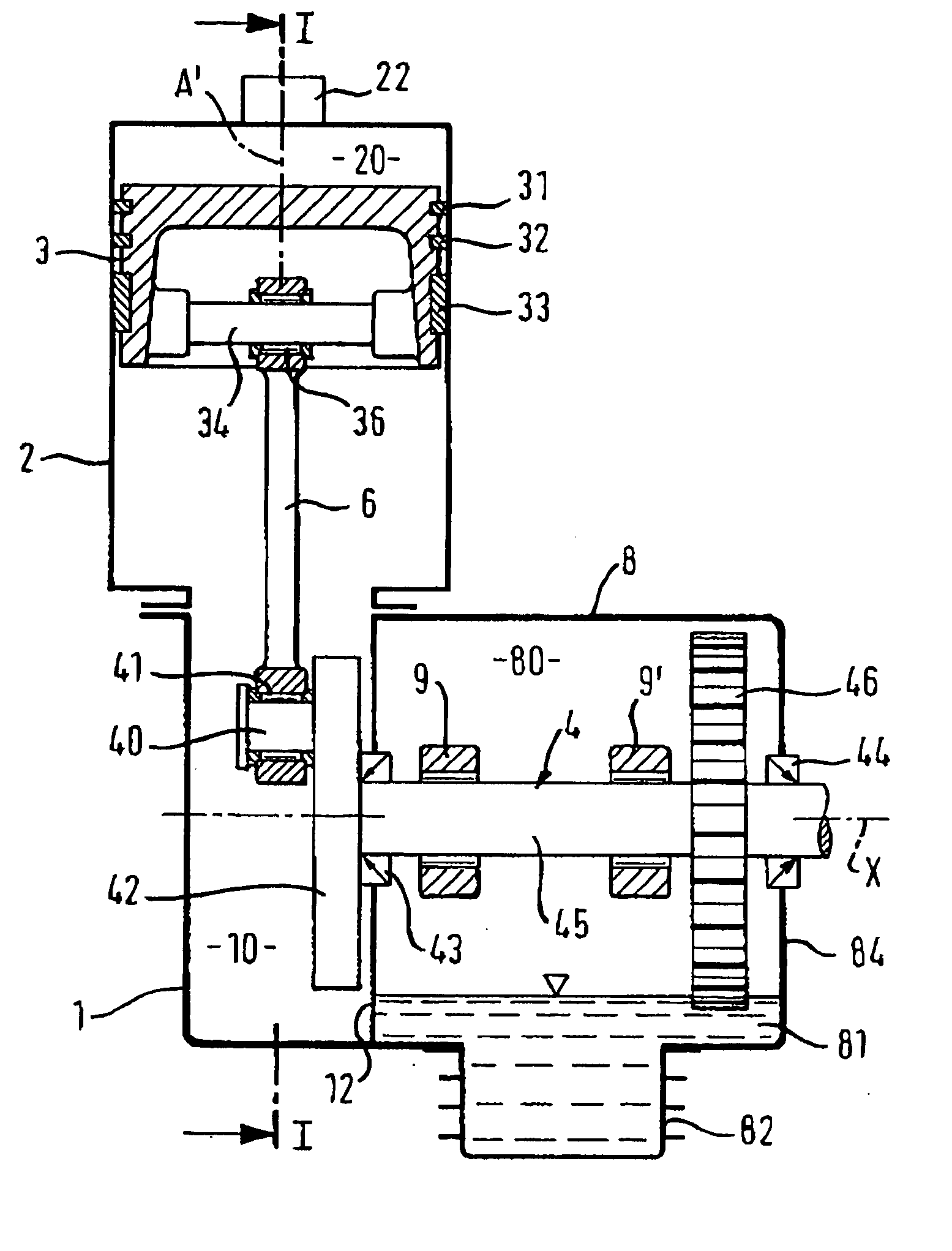
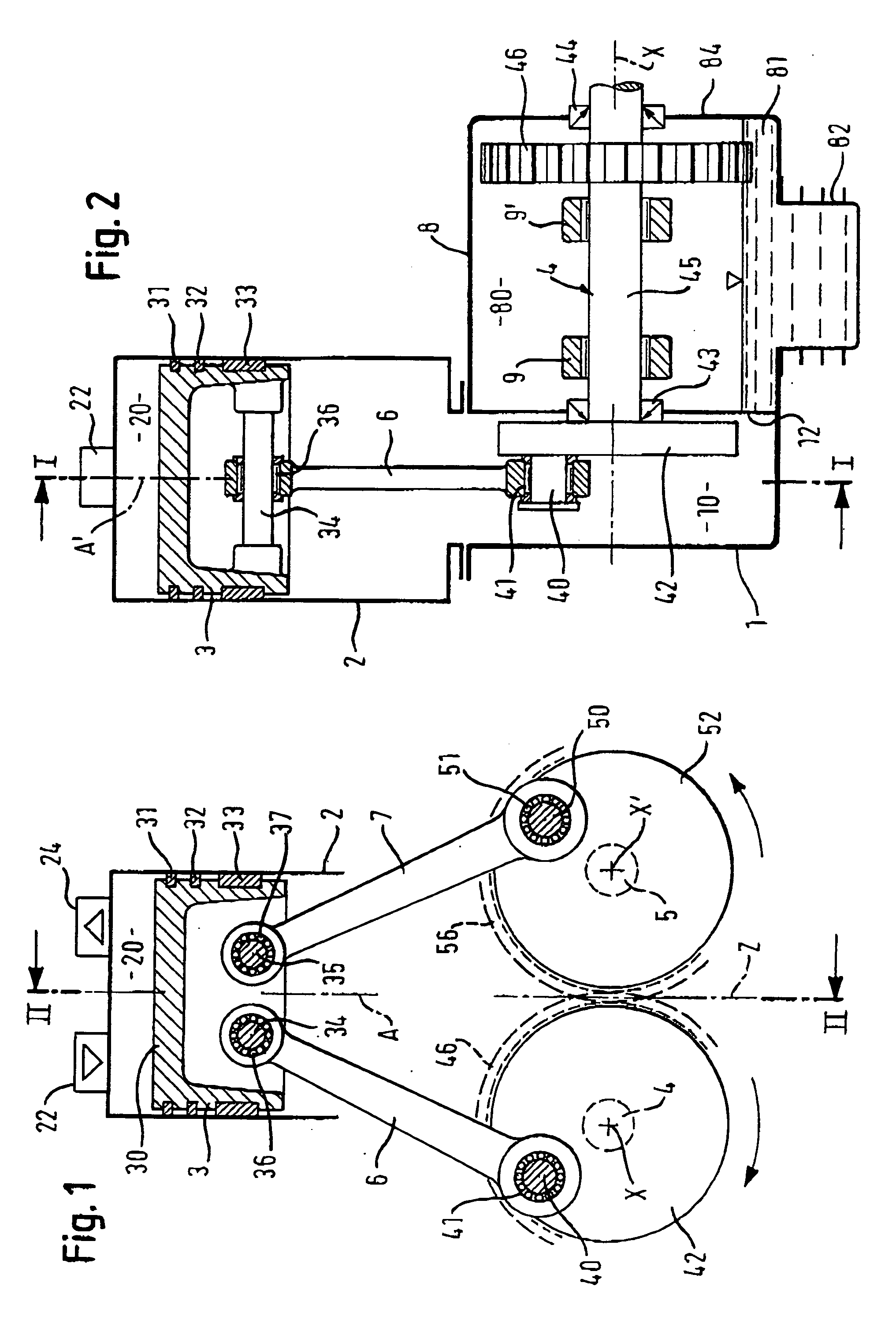
[0025]FIG. 1 schematically illustrates a piston-cylinder unit of a piston engine according to the present invention which includes associated crank gearing. A piston 3 is reciprocably arranged in a cylinder 2 which is coupled to a first housing 1. The walls of the cylinder 2 and the upper surface of piston 30 in cylinder 2 define a cylinder space or a compression space 20. Cylinder 2, which is schematically illustrated in the figures, includes an inlet valve 22 and an outlet valve 24, also schematically shown, which connect the compression space 20 with an intake conduit (not shown) and an exhaust conduit (not shown), respectively.

[0026] Spaced-apart piston rings 31, 32 are arranged on the circumference of piston 3 in the vicinity of its end face 30 (spaced apart). Spaced some distance from piston surface 30 and at a lower portion of the piston is a guide ring 33. Guide ring 33 and / or piston rings 31, 32 are made of a material with self-lubricating characteristics such as, for exam...


PUM


Abstract

A piston engine which has at least one dry-running piston-cylinder unit. It has a first housing (1), at least one cylinder arranged in or on the first housing (1) in which a piston is reciprocably arranged. The piston-cylinder unit further has a first crankshaft (4) and a second crankshaft (5), the first and second crankshafts (4, 5) being arranged parallel to each other and synchronously rotating in opposite directions. The axes of rotation (X, X′) of the crankshafts (4, 5) are arranged parallel to a center plane (Z) of the cylinder, and they are laterally offset relative thereto. First and second piston rods (6, 7) are pivotally connected to piston (3). The first piston rod (6) has a first end pivotally connected to piston (3) and a second end connected to a crank pin (40) of the first crankshaft (4). The second piston rod (7) has a first end that is pivotally connected to piston (3) and a second end that is pivotally connected to a crank pin (50) of the second crankshaft (5). The crankshafts (4, 5) are journalled in a second housing (8) which holds a lubricant. The crankshafts are arranged so that a respective first end of each crankshaft (4, 5) sealingly projects from second housing (8) to prevent the escape of lubricant into first housing (1). The respective piston rods (6, 7) are arranged in the first housing (1) outside second housing (8).

Description

RELATED APPLICATIONS [0001] This application claims priority pursuant to 35 USC §119 from German patent application No. 10 2005 048681.9 filed Oct. 11, 2005. BACKGROUND OF THE INVENTION [0002] The invention relates to a piston engine or machine which has at least one dry-running piston-cylinder unit. [0003] Such piston engines are known and are referred to, for example, as so-called crosshead-piston engines or machines. Such machines employ a two-part piston. A first, upper piston section together with the walls of the cylinder define the cylinder volume. A second, lower piston section extends into the lower portion of the cylinder and is spaced apart from the first piston section by a piston bar. This lower portion of the cylinder forms means for lubricating the second piston area. The lower and upper portions of the cylinder are sealed with respect to each other, and the piston bar between the two cylinder sections extends through the seal. In this manner, the upper section of the...

Claims


Application Information

Patent Timeline
Patent Type & Authority Applications(United States)
IPC IPC(8): F01M1/02F02B75/32F16C9/00F01M9/10F16C7/00F01M11/02
CPCF02B75/065
Inventor BETZMEIR, HELMUT
Owner NEANDER MOTORS
Why Eureka
Try Eureka