Efficient dispersion device

Inactive Publication Date: 2007-04-12
ATLANTA ATTACHMENT
View PDF12 Cites 4 Cited by
  • Summary
  • Abstract
  • Description
  • Claims
  • Application Information

AI Technical Summary

Benefits of technology

[0007] In accordance with the invention, there is therefore provided a fluid conditioning device for increasing fuel burning efficiency and reducing pollutant emissions that is comprised of a hollow housing, at least one flow diverter, and a compound venturi. The hollow housing preferably includes: a first end for receiving a combustible liquid fuel supply and supplying it to an intermediate portion of said housing; an intermediate portion comprising an eddy chamber for receiving fuel from the first end and creating turbulence and mixing within the fuel, said eddy chamber being designed for receiving at least one flow diverter for diverting at least a portion of the flow from the first end in a direction at an angle of from about 30 to about 90 degrees to an original direction of flow from the first end; and a second end for receiving a compound venturi for accepting fuel from the intermediate po

Problems solved by technology

Such inefficiencies also resulted in wasted fuel.
One drawback is that they are complicated and expensive to manufacture.
The device described in U.S. Pat. No. 5,148,794 is even more complex.
Both of these device

Method used


Image

  • Efficient dispersion device
  • Efficient dispersion device
  • Efficient dispersion device

Examples


Embodiment Construction

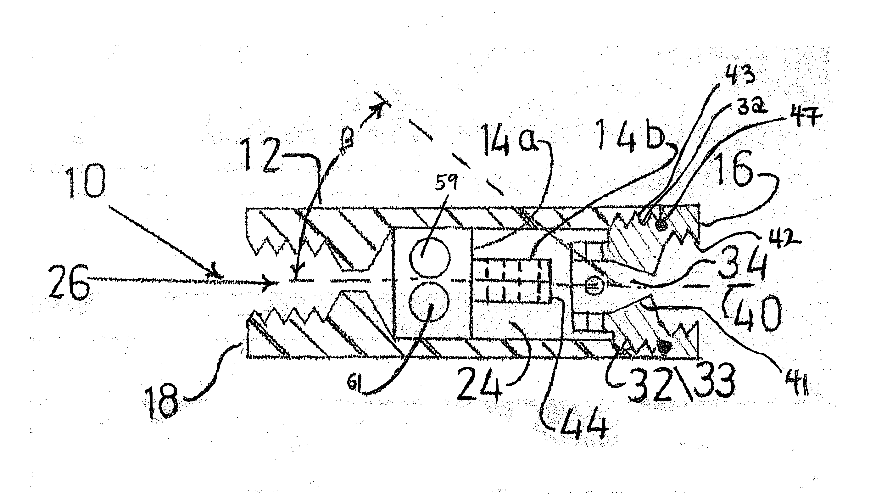
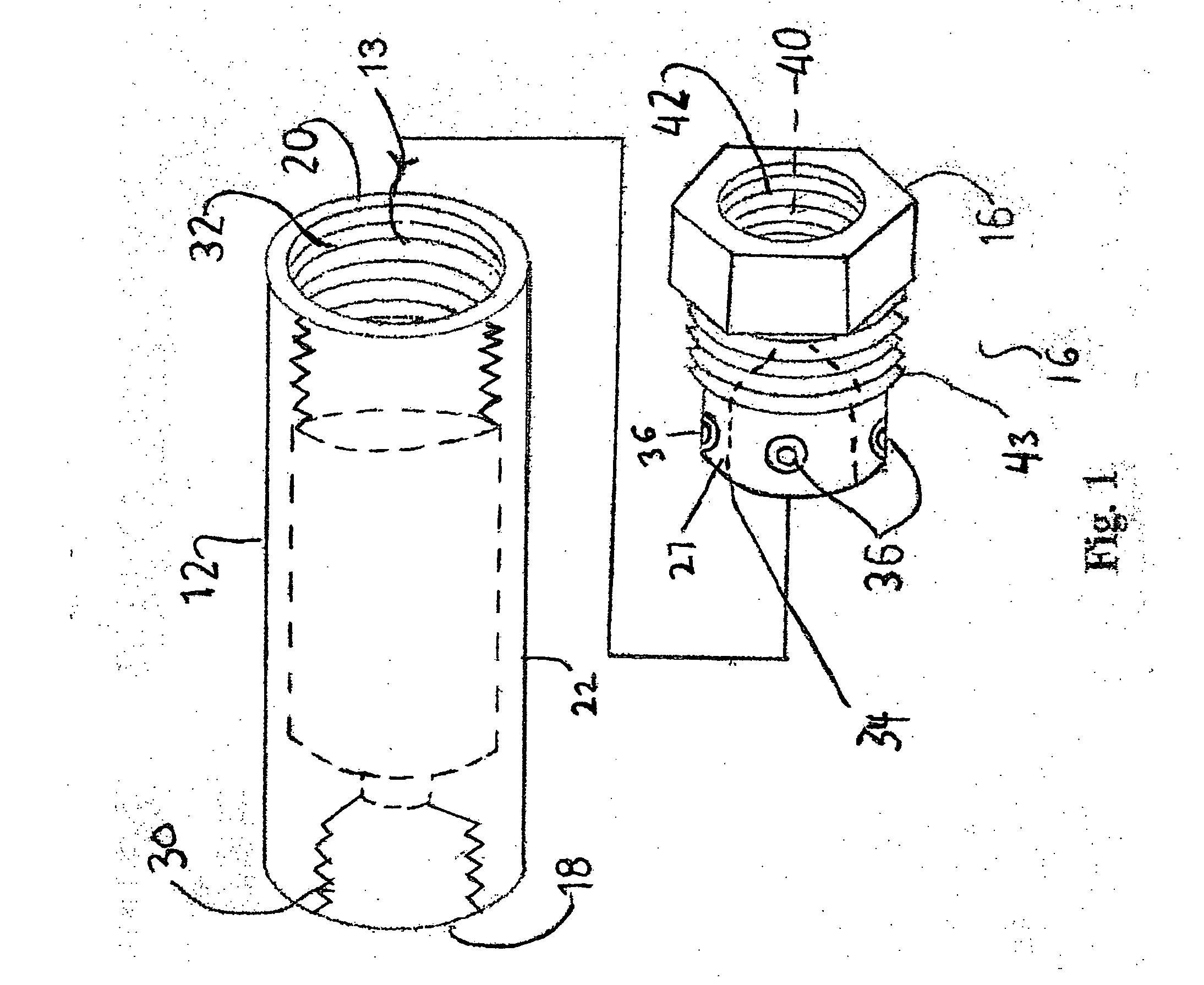
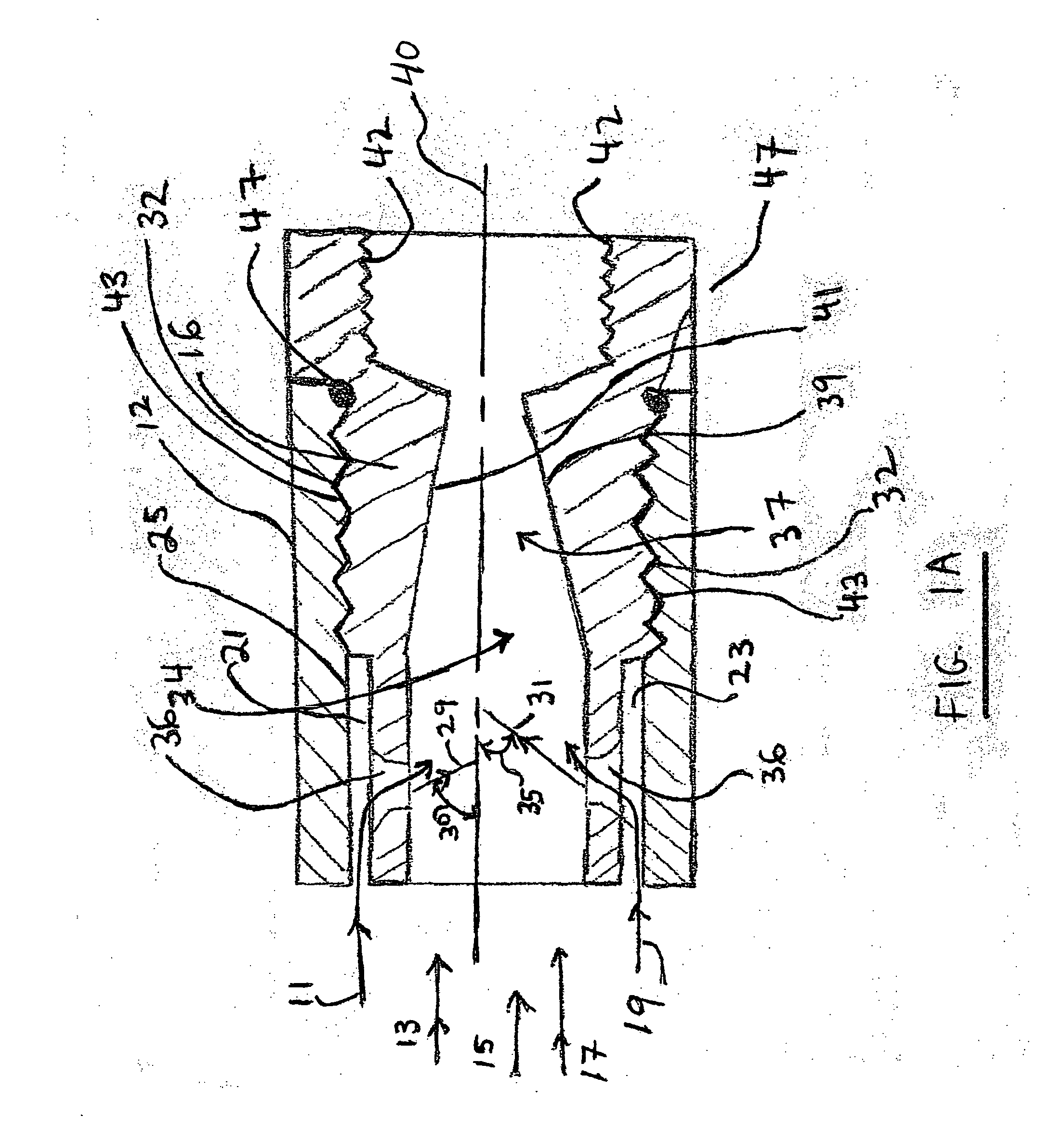
[0020] In one embodiment, the fluid conditioning device of this invention operates through the use of a fuel redirecting apparatus, such as a flow diverter, that redirects a secondary portion of supply fuel flowing through the device to cause it to collide with a primary portion of supply fuel flowing though the device and to create initial turbulent flow; this feature operates in combination with a complex venturi that redirects a portion of the initial turbulent flow through at least one secondary venturi to form secondary venturi flow that impinges the balance of the initial turbulent flow either just before or while the balance of the initial turbulent flow passes through a primary venturi. In one aspect of this embodiment, the redirecting apparatus redirects the secondary supply fuel portion so that it collides with the primary supply fuel portion at an angle of from about 30 to about 90 degrees and most preferably from about 60 to about 90 degrees. Similarly, the secondary ven...


PUM


Abstract

A fuel conditioning device for increasing fuel burning efficiency and reducing pollutant emissions. The device contains: a hollow housing with an interior wall with a first surface roughness, a flow diverter disposed in an intermediate portion of such hollow housing, and a compound venturi disposed in said hollow housing downstream of such flow diverter. The compound venturi contains a multiplicity of radial venturis and a descending conical section disposed downstream from said radial venturis. The descending conical section is defined by a wall whose interior surface has a second surface roughness that is no greater than 0.1 times as great as said first surface roughness.

Description

CROSS-REFERENCE TO RELATED PATENT APPLICATION [0001] This patent application is a continuation-in-part of applicant's copending patent application Ser. No. 11 / 129,964, filed on May 16, 2005.FIELD OF THE INVENTION [0002] A fluid conditioning device comprised of a hollow housing, at least one flow diverter, and a compound venturi. BACKGROUND OF THE INVENTION [0003] Prior art internal combustion engines burned at relatively low efficiencies and thereby produced exhausts comprised of numerous pollutants; these pollutants included, e.g., unburned hydrocarbons, low valence nitrogen oxides (such as NOx), carbon monoxide, and the like. Such inefficiencies also resulted in wasted fuel. [0004] The need to more efficiently utilize hydrocarbon fuels has become painfully evident within the last few years. Efforts have been made to provide internal combustion engines that operate at higher temperatures and that use computer control of fuel air mixes. Automobiles have been provided with after-burn...

Claims


Application Information

Patent Timeline
IPC IPC(8): F02B31/04
CPCF02M33/00F02M69/04F02M37/0017
Inventor SCOUTEN, DOUGLAS G.
Owner ATLANTA ATTACHMENT
Why Eureka
Try Eureka