Gas filling system

a filling system and gas technology, applied in the direction of fluid pressure control, container discharging methods, packaged goods types, etc., can solve the problems of system lack of desired reliability, gas in the receiving tank does create an overheating concern, and none of the systems have recognized the benefit of controlling or the desire to control

Inactive Publication Date: 2007-04-12
AIR PROD & CHEM INC
View PDF9 Cites 58 Cited by
  • Summary
  • Abstract
  • Description
  • Claims
  • Application Information

AI Technical Summary

Benefits of technology

[0013] In the preferred embodiments of this invention the flow controller increases the flow rate of gas when the actual ramp rate is lower than the desired ramp rate and decreases the flow rate of gas when the actual ramp rate is higher than the desired ramp rate.

Problems solved by technology

However, even when charging a receiving tank or vessel with gases other than hydrogen and helium, the adiabatic compression of gas in the receiving tank does create an overheating concern.
This latter system is believed to lack desired reliability, due to the potential for malfunctions associated with the control valve, the PLC, and / or the I / P controller.
Although the prior art does disclose various techniques for attempting to control flow rate of gases, none of the systems have recognized the benefit of controlling, or the desire to control the ramp rate of the gas to limit the temperature rise in a receiving tank, or vessel, and also, to avoid prolonged fill times, particularly when filling large tanks or vessels.

Method used


Image

  • Gas filling system
  • Gas filling system

Examples


Embodiment Construction

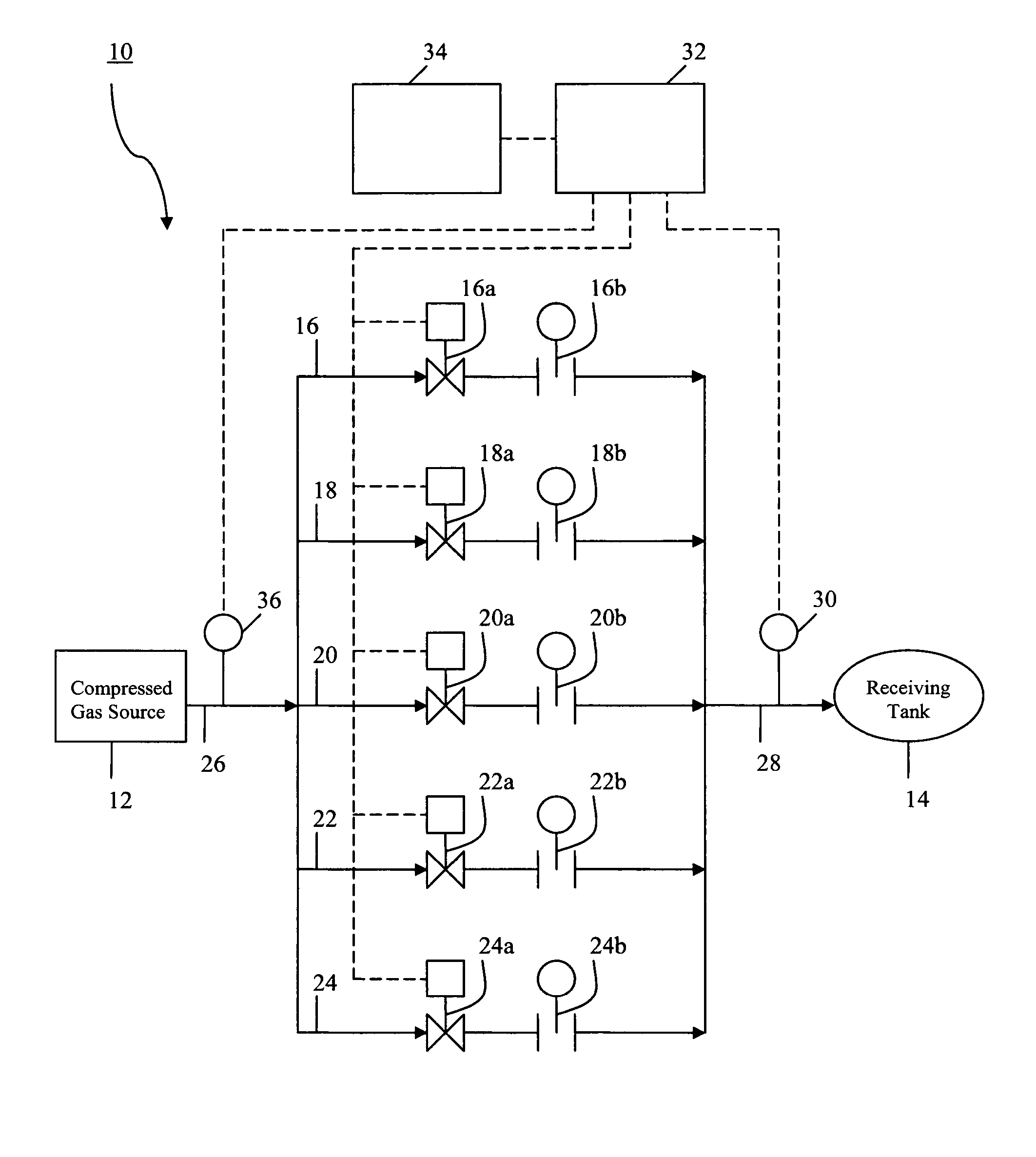
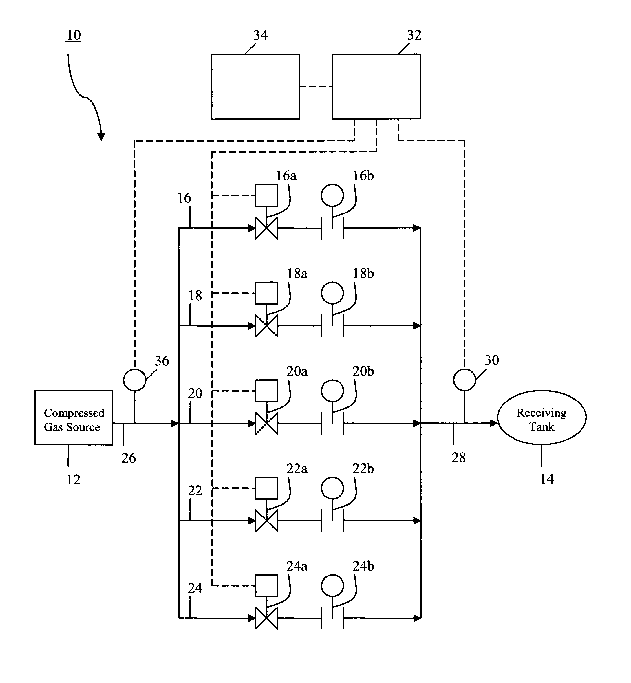
[0026] Referring to the FIGURE, a gas filling system for supplying a gas from a supply of compressed gas 12 to a receiving tank or vessel 14 is schematically illustrated at 10. The gas filling system 10 can be employed to fill a receiving vessel or tank 14 with a variety of different gases, e.g., hydrogen, helium, or natural gas. A particularly desirable use of the filling system 10 is for filling a receiving tank or vessel 14 with hydrogen, and in particular, to a system for filling a receiving tank or vessel of a vehicle with hydrogen.

[0027] Still referring to the FIGURE, the gas filling system 10 includes a supply of gas, e.g., hydrogen, from a pressurized source 12. A variety of pressurized sources can be employed, such as a single storage tank, a number of storage tanks, a pipe line supply, or a supply from a compressor. The gas is directed from the pressurized source 12 to a receiving tank 14 through a plurality of gas transmission lines in parallel with each other. In the il...


PUM

PropertyMeasurementUnit
flow rateaaaaaaaaaa
pressureaaaaaaaaaa
sizeaaaaaaaaaa

Abstract

A system and method for supplying a gas from a supply of compressed gas to a receiving vessel by measuring the pressure of gas being directed into the receiving vessel in successive selected time intervals to determine the actual ramp rate of gas being directed into the receiving vessel and providing means for comparing the actual ramp rate with a desired ramp rate and controlling the gas flow rate in response to that comparison. In a preferred embodiment the pressure of the gas at an upstream end of the system is monitored and directed into a controller and this latter pressure is employed in determining the mass flow of gas into the receiving vessel.

Description

BACKGROUND OF THE INVENTION [0001] This invention relates to a system and method for filling a receiving vessel or tank from a source of compressed gas, and more specifically to a system and method for filling a receiving tank or vessel, e.g., a receiving tank in a vehicle, in a manner that aids in preventing excess heating of the tank and also in eliminating excess fill time, particularly when filling large receiving tanks. [0002] In a system for filling a receiving tank or vessel with compressed gas it is necessary to control the flow rate of the gas so that the receiving tank does not overheat. Overheating occurs as a result of both adiabatic compression of the gas, and, when the gas is hydrogen or helium, by the reverse Joule-Thompson effect. The heat of compression is partially offset by the isentropic expansion cooling within the storage vessel. Moreover, for gases other than hydrogen and helium, a conventional Joule-Thompson effect takes place, which can further mitigate agai...

Claims


Application Information

Patent Timeline
Patent Type & Authority Applications(United States)
IPC IPC(8): B65B3/04
CPCF17C5/007F17C5/06F17C7/00F17C13/025F17C2221/012F17C2221/017F17C2221/033F17C2223/0123F17C2223/036F17C2225/0123F17C2225/036F17C2250/032F17C2250/043F17C2250/0626F17C2260/023F17C2260/025F17C2270/0139F17C2270/0168Y02E60/321G05D16/204Y02E60/32
Inventor COHEN, JOSEPH PERRYFARESE, DAVID JOHN
Owner AIR PROD & CHEM INC
Why Eureka
Try Eureka