Printhead maintenance station configured for air blast cleaning of printhead

a technology for air blast cleaning and printheads, applied in printing and other directions, can solve the problems of paper dust, slow print speed of all commercially available inkjet printers, and failure of printheads, and achieve the effect of improving print speed and page width, reducing maintenance costs, and improving service li

Active Publication Date: 2007-04-12
SILVERBROOK RES PTY LTD +1
View PDF1 Cites 9 Cited by
  • Summary
  • Abstract
  • Description
  • Claims
  • Application Information

AI Technical Summary

Benefits of technology

[0051] Optionally, air is blasted through a blast channel adjacent the ink ejection face. Typically, the blast channel is defined by a constriction member spaced apart from the face. The constriction member provides a constricted blast channel, which has the effect of accelerating air flow across the ink ejection face according to Bernoulli's law. Optionally, air flow rates of 2

Problems solved by technology

However, all commercially available inkjet printers suffer from slow print speeds, because the printhead must scan across a stationary sheet of paper.
Printhead failure may be caused by, for example, printhead face flooding, dried-up nozzles (due to evaporation of water from the nozzles—a phenomenon known in the art as decap), or particulates fouling nozzles.
Particulates, in the form of paper dust, are a particular problem in high-speed pagewidth printing.
Frictional contact of the paper with the paper guide generates large quantities of paper dust compared to traditional scanning inkjet printheads, where paper is fed much more slowly.
Hence, pagewidth printheads tend to

Method used


Image

  • Printhead maintenance station configured for air blast cleaning of printhead
  • Printhead maintenance station configured for air blast cleaning of printhead
  • Printhead maintenance station configured for air blast cleaning of printhead

Examples


Embodiment Construction

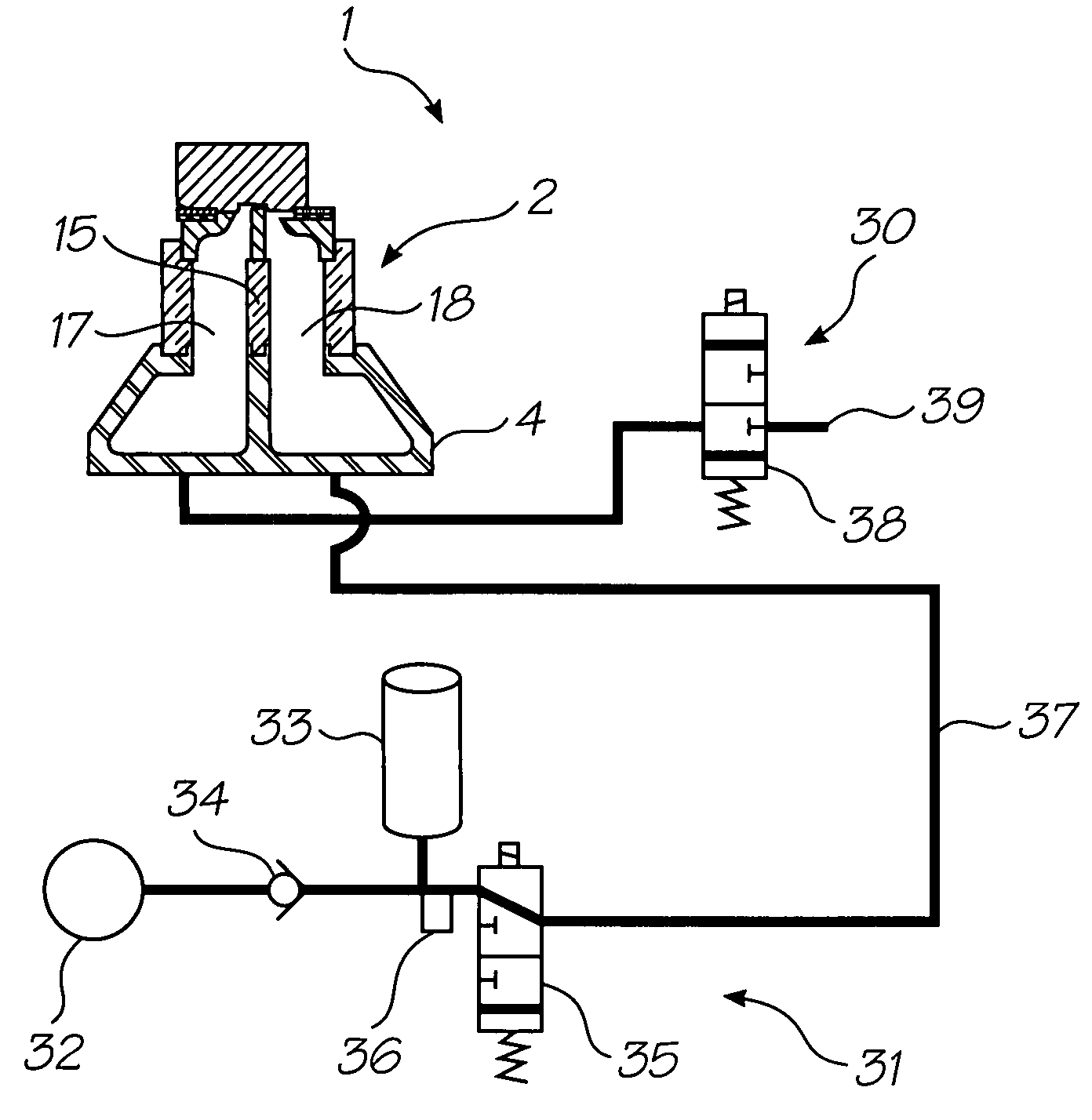
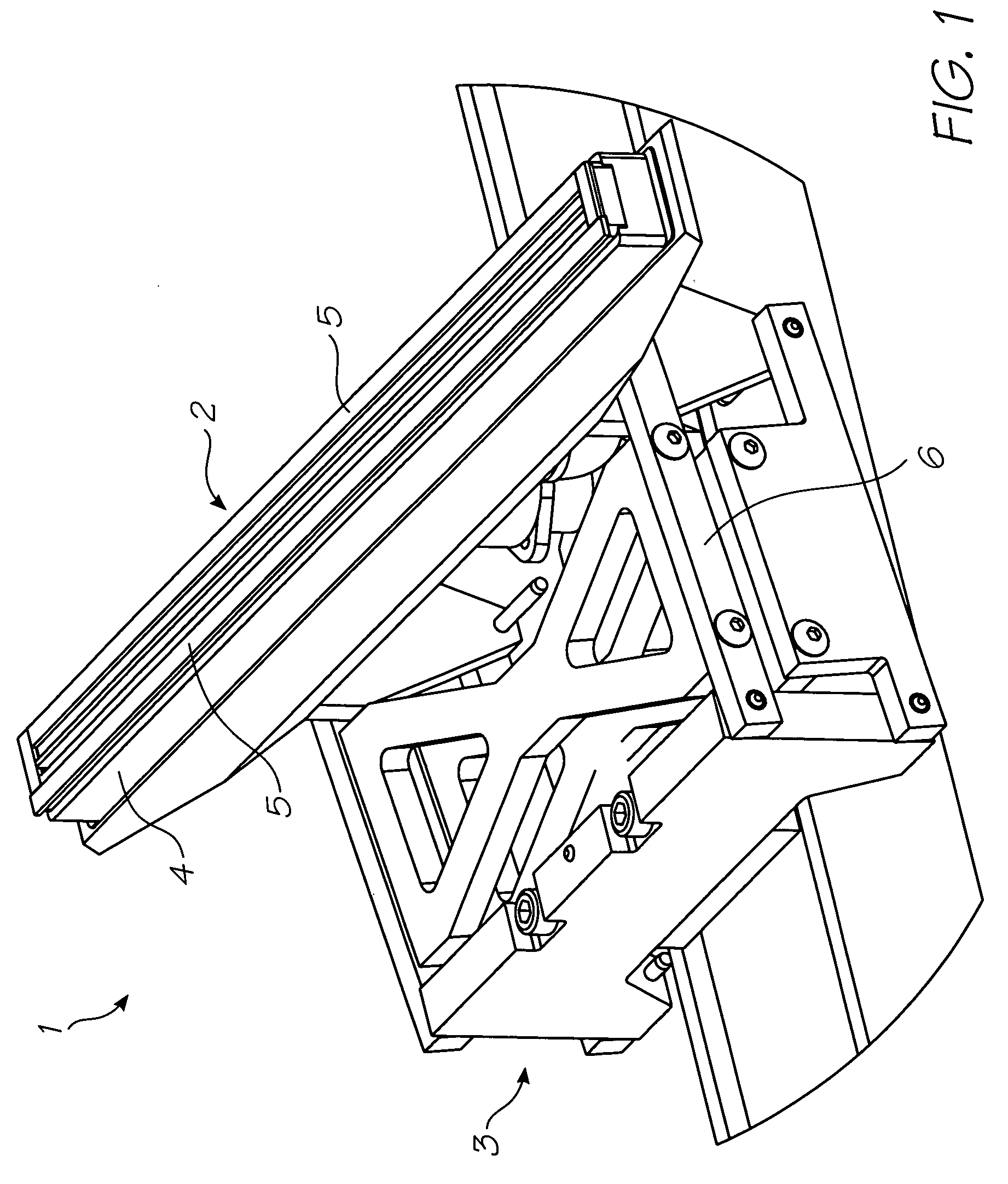
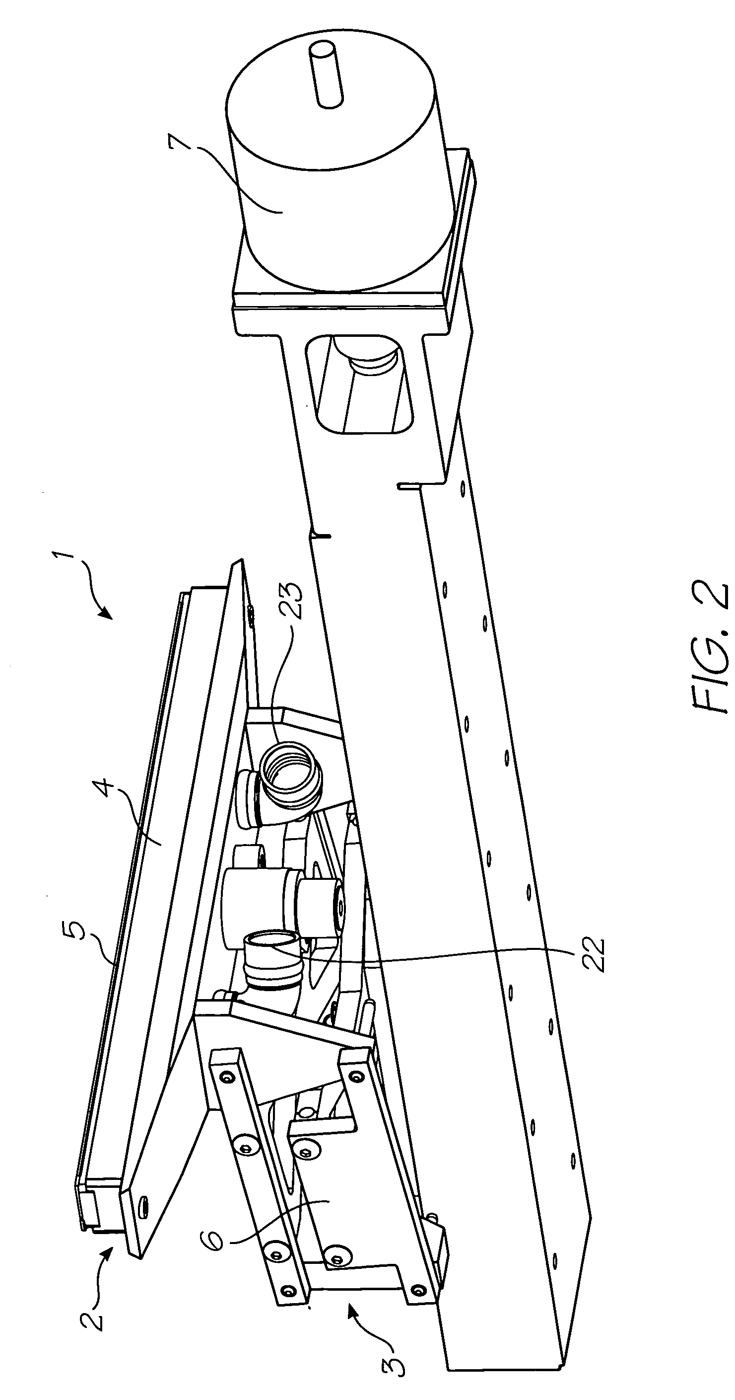
[0272] Referring to FIGS. 1 and 2, there is shown part of a printhead maintenance station 1 comprising a capper 2 and an engagement mechanism 3. The capper 2 takes the form of an elongate capping chamber 4 having a perimeter gasket 5 fixed around one end. The capping chamber 4 with gasket 5 is configured to fit and form a seal around a pagewidth printhead 10 (see FIGS. 3 and 4).

[0273] In the embodiment shown, the engagement mechanism 3 takes the form of a pantograph 6, which raises and lowers the capper 2 into sealing engagement and out of engagement from around the printhead 10. The pantograph 6 is actuated using a motor 7, which raises and lowers the pantograph via a cam arrangement (not shown). Other types of engagement mechanism suitable for raising and lowering the capper 2 will, of course, be readily apparent to the person skilled in the art.

[0274] Referring to FIGS. 3 and 4, the capper 2, engaged around the printhead 10, is shown in more detail. The printhead 10 is mounted ...


PUM


Abstract

A printhead maintenance station for maintaining a printhead in an operable condition is provided. The maintenance station comprises a capper sealingly engageable around the printhead. The capper comprises a constriction member for defining a blast channel adjacent an ink ejection face of the printhead. The maintenance station further comprises a vacuum system in fluid communication with the capper and an engagement mechanism. The engagement mechanism moves the capper between a first position in which the capper is sealingly engaged around the printhead and a second position in which the capper is disengaged from around the printhead.

Description

CROSS REFERENCES TO RELATED APPLICATIONS [0001] Various methods, systems and apparatus relating to the present invention are disclosed in the following U.S. patents / patent applications filed by the applicant or assignee of the present invention: 09 / 517539656685809 / 11276263319466246970644252509 / 51738409 / 505951637435409 / 51760809 / 50514710 / 20356467578326334190674533109 / 51754110 / 20355910 / 20356010 / 63626310 / 63628310 / 86660810 / 90288910 / 90283310 / 94065310 / 94285810 / 72718110 / 72716210 / 72716310 / 72724510 / 72720410 / 72723310 / 72728010 / 72715710 / 72717810 / 72721010 / 72725710 / 72723810 / 72725110 / 72715910 / 72718010 / 72717910 / 72719210 / 72727410 / 72716410 / 72716110 / 72719810 / 72715810 / 75453610 / 75493810 / 72722710 / 72716010 / 93472011 / 212,70210 / 296522679521510 / 29653509 / 57510910 / 29652509 / 57511009 / 607985639833263945736622923674776010 / 18945910 / 88488110 / 94394110 / 94929411 / 03986611 / 12301111 / 12301011 / 14476911 / 14823710 / 92284610 / 92284510 / 85452110 / 85452210 / 85448810 / 85448710 / 85450310 / 85450410 / 85450910 / 85451010 / 85449610 / 85449710 / 8544951...

Claims


Application Information

Patent Timeline
IPC IPC(8): B41J2/165
CPCB41J2/16511
Inventor KARPPINEN, VESASILVERBROOK, KIA
Owner SILVERBROOK RES PTY LTD
Why Eureka
Try Eureka