Lensless imaging with controllable apertures

a technology of controllable apertures and lensless imaging, which is applied in the field of lensless imaging, can solve the problems of limited control of the geometry and photometry of the imaging process, limited mechanical constraints of the motor, and large mechanical constraints of the motor, and achieves the effect of high flexibility

Inactive Publication Date: 2007-04-12
THE TRUSTEES OF COLUMBIA UNIV IN THE CITY OF NEW YORK
View PDF22 Cites 46 Cited by
  • Summary
  • Abstract
  • Description
  • Claims
  • Application Information

AI Technical Summary

Benefits of technology

[0008] Embodiments of the present invention provide highly flexible lensless imaging devices and methods of acquiring images that overcome many of the limitations of conventional cameras. In some embodiments, the devices include an image detector and one or more light attenuating layers which can be parallel to each other. The transmittance of the light attenuating layers is controllable in space and time. By applying different transmittance patterns to the light attenuating layers, it is possible to modulate the incoming light in useful ways and acquire images that are not possible to acquire with conventional cameras. The light attenuating layers can be liquid crystal displays made from liquid crystal sheets, digital micromirror devices, or liquid crystal on silicon devices.
[0009] In some embodiments, the device can change its viewing direction instantaneously to arbitrary directions by merely modifying the transmittance pattern of the aperture. In other embodiments, the device can acquire images of disjoint regions of interest in a scene without having to acquire the regions in between. Therefore, the device can select which parts of the scene to acquire an image of at each time instance, and can simultaneously acquire images of far apart moving objects with higher resolution.
[0013] In some embodiments, the light attenuating layer controller of the device is further configured to create and / or move an aperture within the first light attenuating layer, the aperture including at least one element of the first light attenuating layer having a higher transmittance than elements surrounding the aperture. The device can further include an image analyzer coupled to the image detector and configured to detect an image of a moving object within an image acquired by the image detector, a position determination component coupled to the image analyzer and configured to determine the position of the moving object image within the acquired image, and a view determination component coupled to the position determination component and configured to determine a field of view expected to contain the moving object at a later time based on the determined position. The light attenuating layer controller can be configured to move the aperture to another position within the light attenuating layer corresponding to the determined field of view, thereby enabling the image detector to acquire another image containing the moving object at the later time.
[0015] The device can further include an image analyzer coupled to the image detector and configured to detect an image of a moving object within an image acquired by the image detector, a position determination component coupled with the image analyzer and configured to determine the position of the moving object image within the acquired image, and a view determination component coupled with the position determination component and configured to determine a field of view expected to contain the moving object at a later time based on the determined position. The light attenuating layer controller can be further configured to move the apertures to change one of the plurality of disjointed fields of view to the determined field of view, thereby enabling the image detector to acquire another image containing the moving object at the later time.
[0017] In some embodiments, the device can further include an image processing component. The image detector can acquire an image of distinct parts of a scene at different focal lengths, and the image processing component can be configured to computationally remove blur in the image acquired by the image detector.

Problems solved by technology

For example, lens cameras severely restrict the geometry and photometry of the imaging process.
As a result, conventional video cameras provide limited control over their imaging properties.
Motors (e.g., pan-tilt motors) can be used to move lens 101 and / or image detector 103, however, motors are limited by mechanical constraints and produce motion blur.
However, conventional pinhole cameras also suffer from the kinds of inflexibility facing lens cameras.

Method used


Image

  • Lensless imaging with controllable apertures
  • Lensless imaging with controllable apertures
  • Lensless imaging with controllable apertures

Examples


Embodiment Construction

, including the description of various embodiments of the invention, will be best understood when read in reference to the accompanying figures wherein:

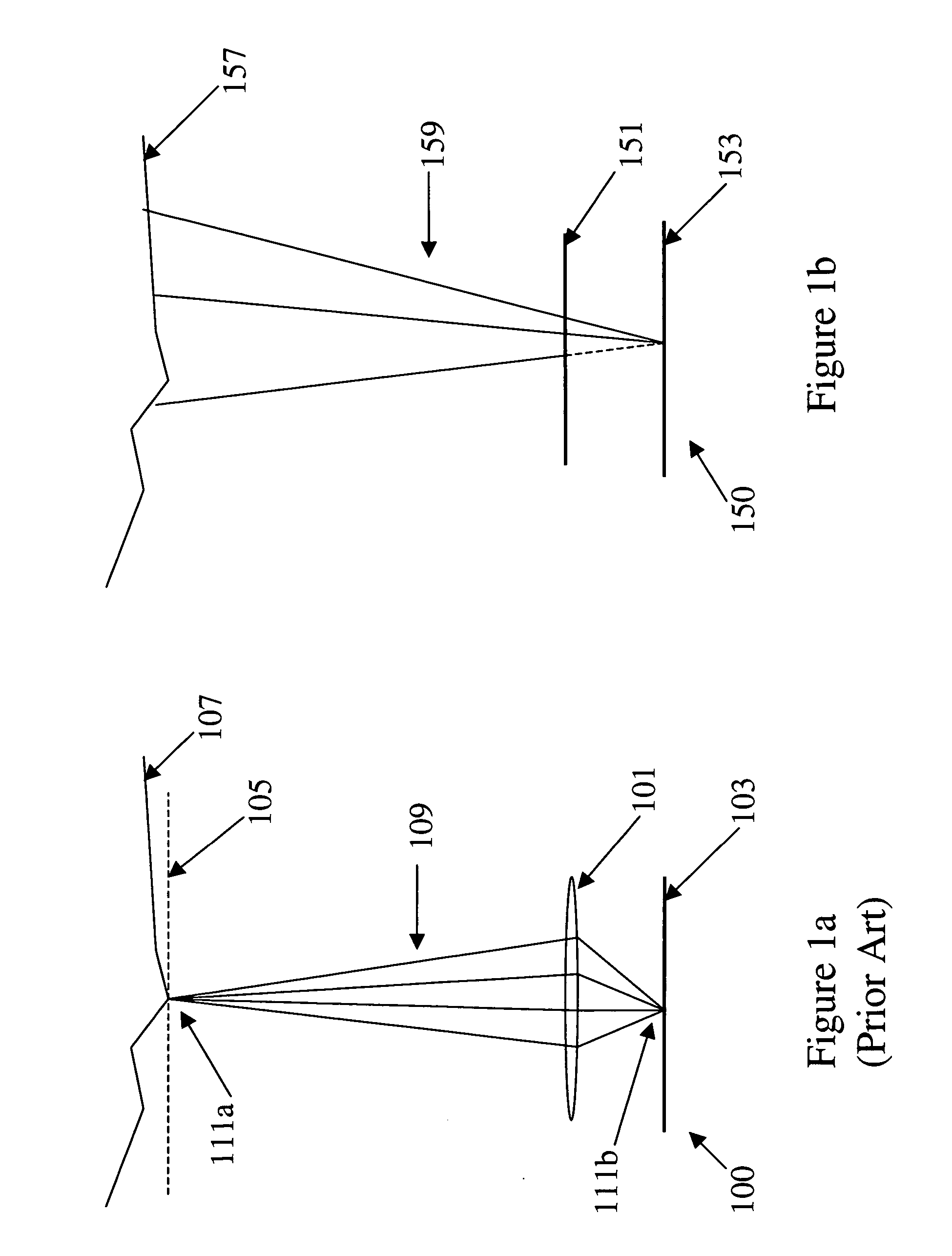
[0022]FIG. 1a is a cross-sectional view illustrating a conventional ideal lens camera;

[0023]FIG. 1b is a cross-sectional view of a lensless imaging device according to various embodiments of the present invention;

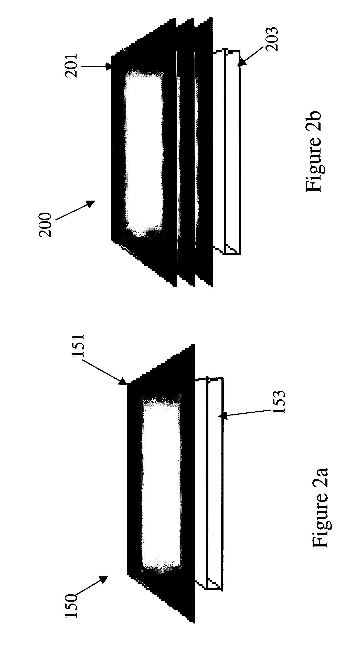
[0024]FIG. 2a is a side view of the device illustrated in FIG. 1b;

[0025]FIG. 2b is a side view of another lensless imaging device according to various embodiments of the present invention;

[0026]FIG. 3 is a side view of yet another lensless imaging device according to various embodiments of the present invention;

[0027]FIG. 4 illustrates a patch taken from an acquired image that would be produced in certain embodiments of the present invention;

[0028]FIG. 5 is a diagram illustrating a prototype implementation of a lensless imaging device according to various embodiments of the present invention;

[0029]FIG. 6a is a diagram...


PUM


Abstract

Embodiments of the present invention provide a lensless optical device for acquiring an image. The device can include a light attenuating layer having a plurality of elements, where transmittance of each of the plurality of elements is controllable, and an image detector disposed at a distance from the light attenuating layer, the image detector configured to acquire an image with light that passes through the light attenuating layer. The device also can include a light attenuating layer controller configured to simultaneously control transmittance of each of the plurality of elements independent of each other. Methods of detecting and tracking an object in a scene are also disclosed.

Description

CROSS-REFERENCE TO RELATED APPLICATION [0001] This application claims priority under 35 U.S.C. § 119(e) from U.S. Provisional Patent Application No. 60 / 662,270, filed on Mar. 16, 2005, which is hereby incorporated by reference in its entirety.STATEMENT REGRADING FEDERALLY SPONSORED RESEARCH OR DEVELOPMENT [0002] The government may have certain rights in the present invention pursuant to a grant by the NSF / ITR, Grant No. ITR-00-85864.FIELD OF THE INVENTION [0003] The present invention relates to lensless imaging. More particularly, embodiments of the present invention relate to lensless imaging devices and methods for acquiring images using a light attenuating layer with controllable apertures. BACKGROUND OF THE INVENTION [0004] Most conventional cameras use lenses to focus light on image planes to form bright and sharp images. In spite of the desirable features that lenses provide, lenses constrain the mapping from the scene to the image. For example, lens cameras severely restrict ...

Claims


Application Information

Patent Timeline
Patent Type & Authority Applications(United States)
IPC IPC(8): H04N1/04
CPCH04N1/04H04N5/2254H04N2101/00H04N2201/02493H04N23/55
Inventor ZOMET, ASAFNAYAR, SHREE K.
Owner THE TRUSTEES OF COLUMBIA UNIV IN THE CITY OF NEW YORK
Why Eureka
Try Eureka