
LED light source module with high efficiency heat dissipation

a technology of led light source module and heat dissipation effect, which is applied in the direction of semiconductor devices for light source, light and heating apparatus, printed element electric connection formation, etc., can solve the problem that the heat generated by the emitter leds b>12/b> cannot be effectively dissipated, the major technical barrier needs to be resolved, and even affect the overall reliability of the lighting unit. problem, to achieve the effect of high heat dissipation efficiency, high thermal conductivity problem

Inactive Publication Date: 2007-04-12
OPTO TECH
View PDF7 Cites 129 Cited by
  • Summary
  • Abstract
  • Description
  • Claims
  • Application Information

AI Technical Summary

Benefits of technology

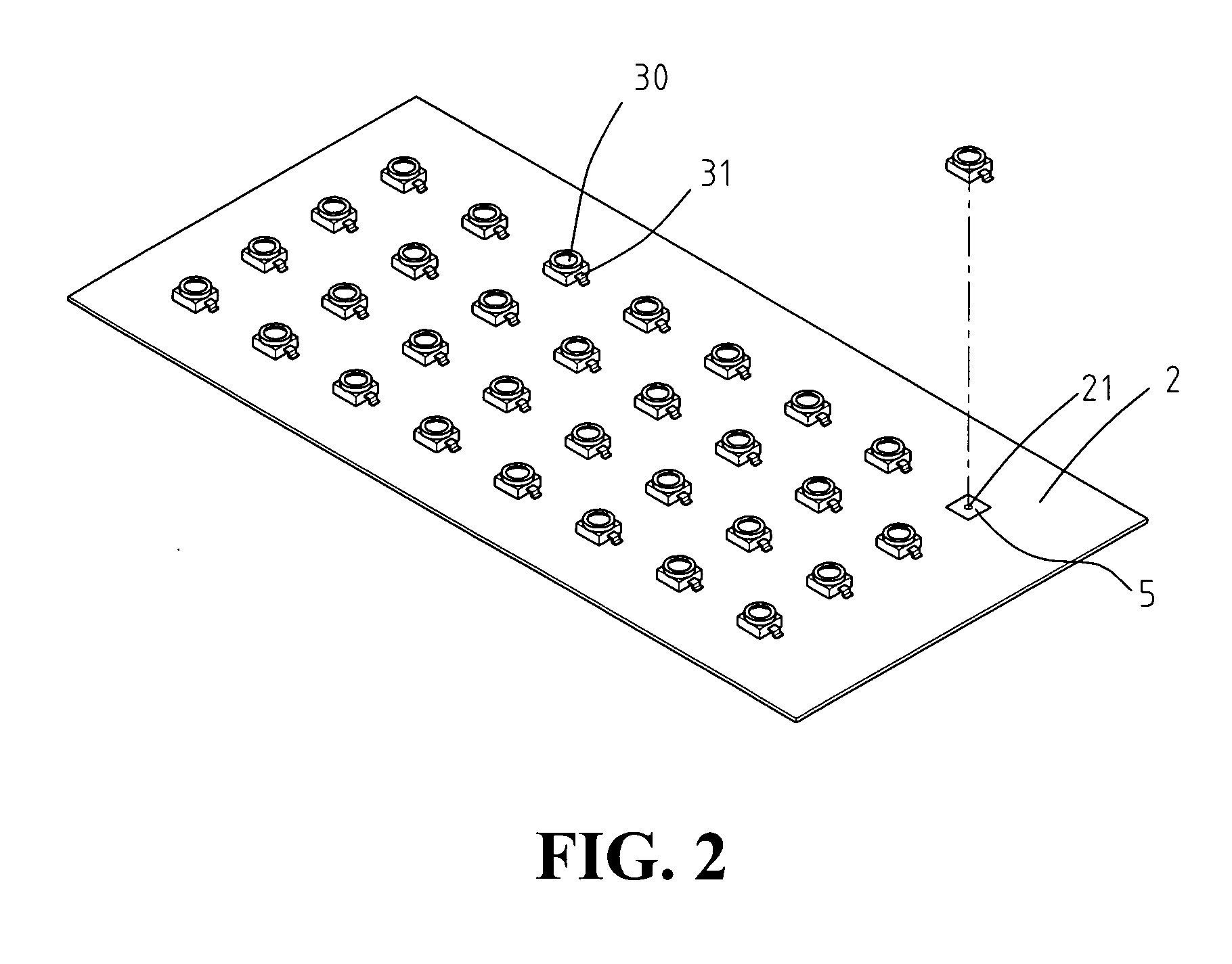
[0004] The present invention provides an LED light source module featured with high heat dissipation. The high efficient heat dissipation effect is accomplished as follows: one or a few punctured holes are made on the printed circuit board right underneath each emitter LED; the surface of the punctured holes is coated with material with high thermal conductivity; alternatively, the whole punctured holes are filled with materials with high thermal conductivity. This thus facilitates efficient heat dissipation into the surrounding atmosphere.

Problems solved by technology

To efficiently use LEDs for general light source, however, there is one major technical barrier needs to be resolved.
Taking the LED arrays used for street lighting as an example, without an efficient heat dissipating facility, the resulting mass heat greatly shortens the life spend of the LED arrays and even affects the overall reliability of the whole lighting unit.
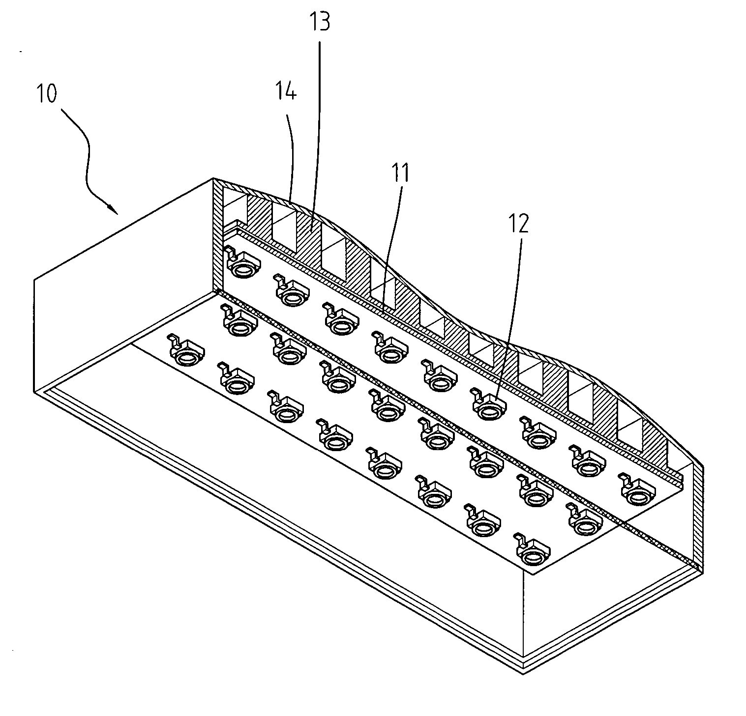
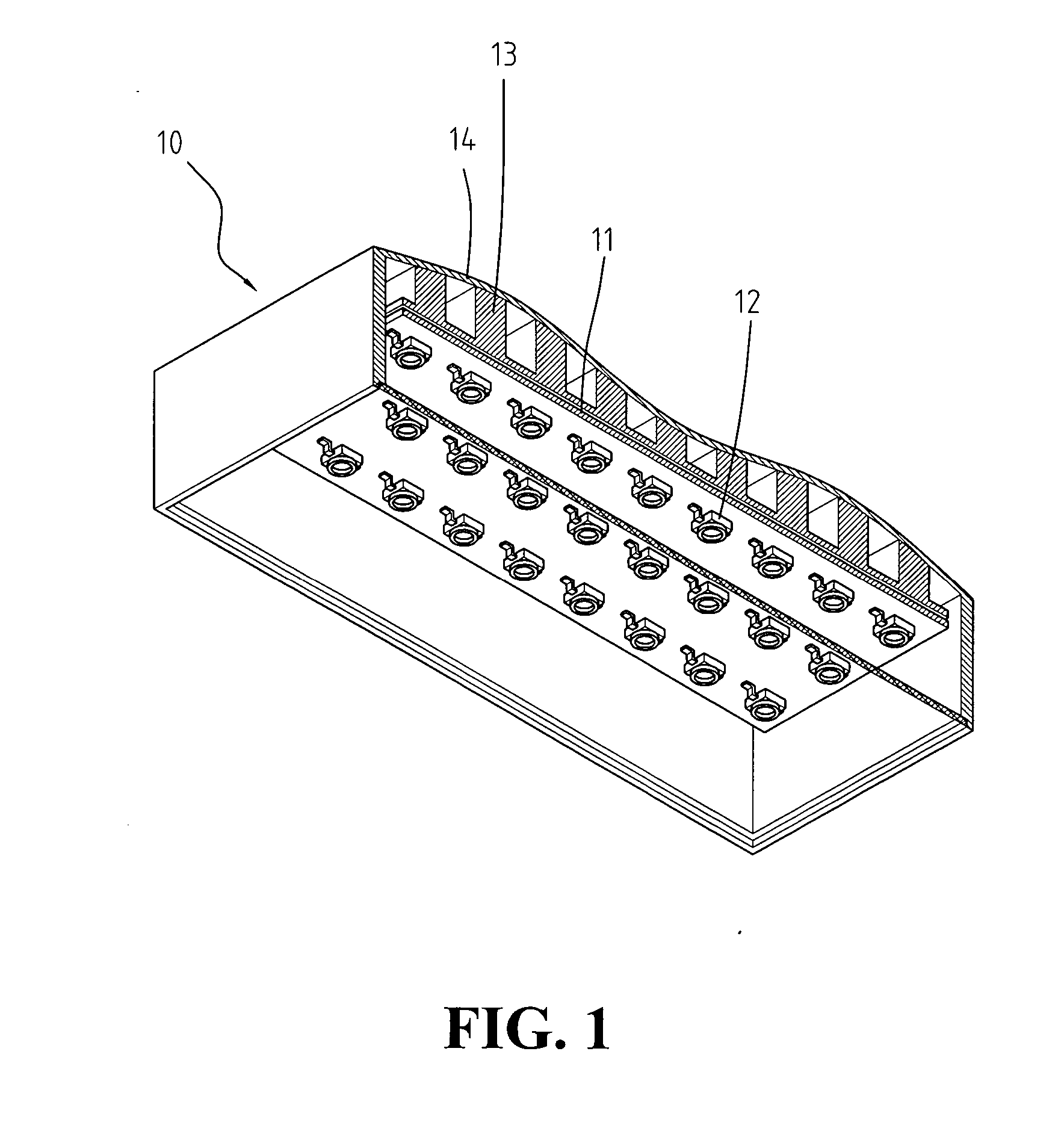
When the printed circuit boards are made of FR4, FR5 or other fibril materials with poor heat conductivity, the heat generated from the emitter LEDs 12 cannot be effectively dissipated.

Method used


Image

  • LED light source module with high efficiency heat dissipation
  • LED light source module with high efficiency heat dissipation
  • LED light source module with high efficiency heat dissipation

Examples


Embodiment Construction

[0016]FIG. 2 and FIG. 3A illustrate a 3-D perspective view and the structure of a cross-sectional views of the present invention, respectively. The present invention comprises one printed circuit board 2 and an LED array composing of multiple emitter LEDs 30. Referring to FIG. 3A, on the said printed circuit board 2, where right underneath each emitter LED 30 locates, there is a least one punctured hole 21. (In FIG. 3B, there are two punctured holes 21 on the printed circuit board where right underneath each emitter LED 30). The surface of each punctured hole 21 is coated with thermal conductive layer 22. The thermal conductive layer can be made of material with high thermal conductivity, such as copper, silver, diamond thin film, thermal paste, etc. In the first embodiment of the present invention, the punctured holes 21 are hollow, with only the surface of holes coated with thermal conductive layer 22. Alternatively, the thermal conductive layer can fill up the whole hole 21 (as s...


PUM


Abstract

The present invention provides a light source module with high efficiency, super bright LEDs featured with efficient heat dissipation. This invention comprises a printed circuit board installed with an LED array which is composed of multiple emitter LEDs. To achieve efficient effect for heat dissipation, there is more than one hole punctured on the printed circuit board right underneath each emitter LED. The surface of each punctured hole is coated with thermal conductive layer such that the accumulative heat generated by the high power LEDs can be effectively dissipated through the conductive layer.

Description

FIELD OF THE INVENTION [0001] The present invention generally relates to a light emitting diode (LED) light source module, and more specifically to an efficient heat resistant lighting module, and its application lighting fixtures with high power and super bright LED light source with efficient heat dissipation. BACKGROUND OF THE INVENTION [0002] The maturity of the light emitting diode (LED) technology has set fire on the global revolution of the lighting industries. Almost in all aspects of daily lives, such as traffic lights, large screen display, home / office lighting, automobile lighting, commercial art lighting, etc., it is an obvious trend that LEDs will replace all conventional lighting facilities. To efficiently use LEDs for general light source, however, there is one major technical barrier needs to be resolved. Brighter LEDs need higher power and also generate mass heat. Taking the LED arrays used for street lighting as an example, without an efficient heat dissipating fac...

Claims


Application Information

Patent Timeline
IPC IPC(8): F21V29/00
CPCF21K9/00F21V29/85F21Y2101/02H05K1/0206H05K1/189H05K3/0061H05K3/305H05K3/4069H05K3/42H05K2201/0209H05K2201/09563H05K2201/0959H05K2201/10106F21V29/20F21V29/74F21V29/004F21Y2115/10F21V29/503F21V29/70
Inventor CHUNG, HUAI-KUYANG, CHENG-WEILIN, CHIEN-HUNGTU, SHUN-LIHWANG, HUNG-TUNG
Owner OPTO TECH
Learn More