
High-voltage detecting circuit for saving power in standby mode

a high-voltage detection and power saving technology, applied in the direction of excess voltage responsive arrangements, emergency protective arrangements for limiting excess voltage/current, instruments, etc., can solve the problems of excessive consumption of power during standby mode, drawbacks that fail to meet the eager call in the commercial market, and power loss of electronic devices during standby mode. to achieve the effect of eliminating power loss

Active Publication Date: 2007-04-12
DELTA ELECTRONICS INC
View PDF5 Cites 3 Cited by
  • Summary
  • Abstract
  • Description
  • Claims
  • Application Information

AI Technical Summary

Benefits of technology

[0020] The conception of the present invention utilizes the command of the PFC IC in the power supply to control the conduction of the high-voltage detecting circuit so as to eliminate the power loss of the high-voltage detecting module when the power supply stays at the standby mode.
[0021] In accordance with an aspect of the present invention, a high-voltage detecting circuit is provided. The provided high-voltage detecting circuit contains a high-voltage detecting module, a switch module and a control module, wherein the high-voltage detecting module is composed of a plurality of resistors for detecting a high-voltage power supply, the control terminal of the control module is controlled by the power supply to shut down the switch module at the standby mode so as to eliminate the standby power loss of the high-voltage detecting module.

Problems solved by technology

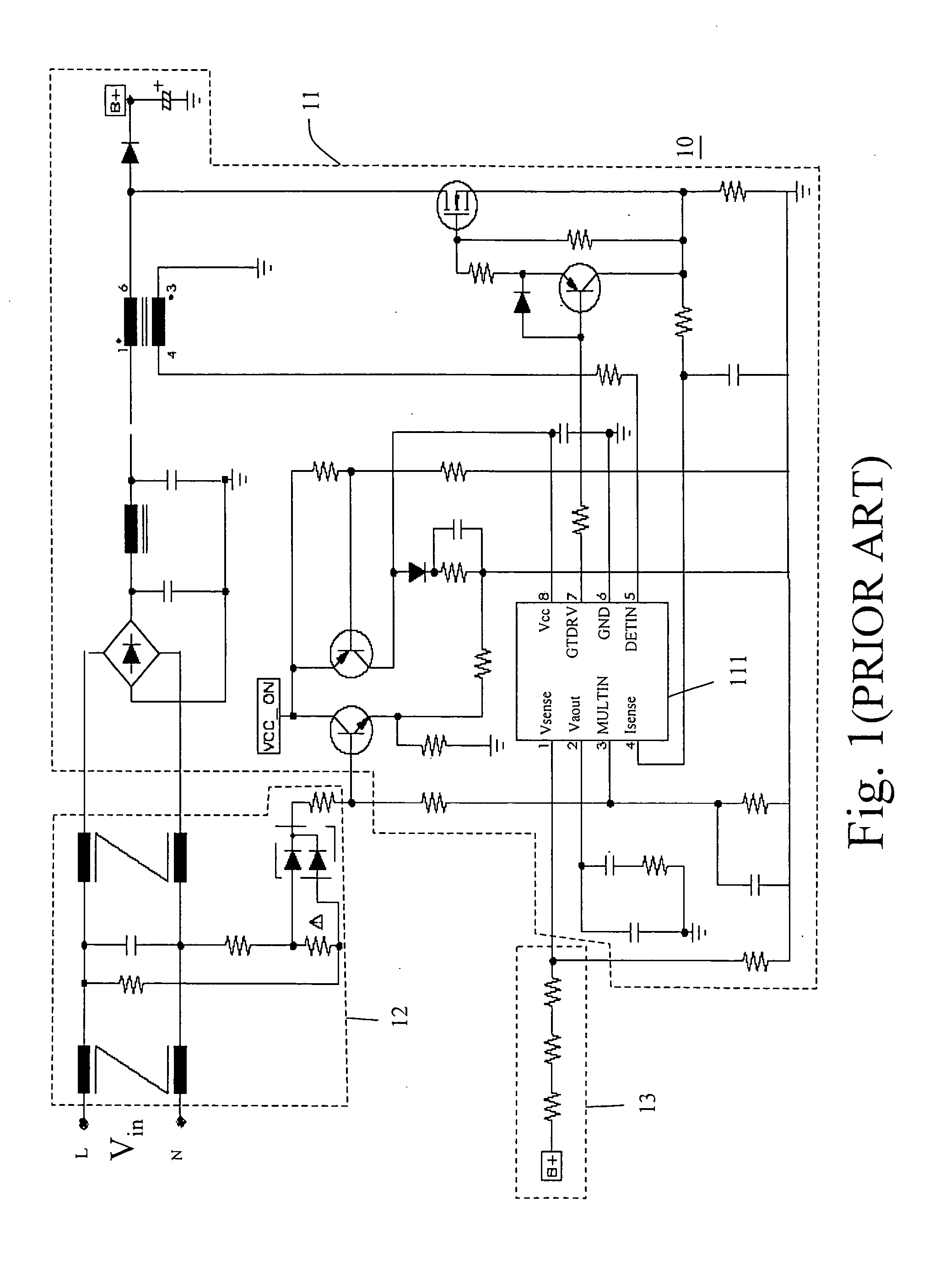
Whereas, the high-voltage detecting circuit 13 purely constituted by the resistors is used to detect a high-voltage power supply, meaning that it will consume considerable power during the standby mode.
Such drawback fails to meet the eager call in the commercial market attempting to lower the standby power loss of the electronic device.
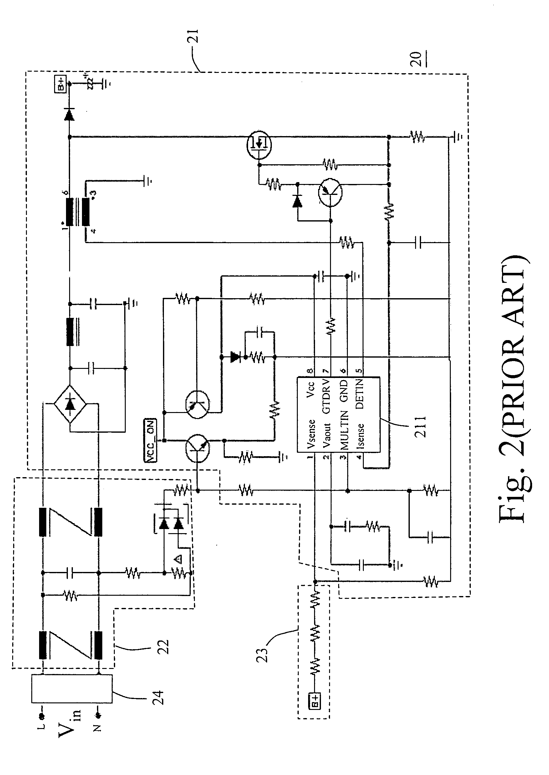
As a result, the standby power loss is only 70 mW, which is the standby power loss of the IC in the main circuit 21 for powering off the system.
Although the power supply 20 in FIG. 2 has improved the disadvantage of the power supply 10 in FIG. 1, it still leads to the following drawbacks: (1) The cost of the relay, which is relatively higher than that of the resistor, transistor switch, etc., impacts on the cost-down planning of the manufacturer.
(2) The reliability of the relay is an issue; in other words, while the total operation time thereof accumulates, the circuit joint thereof will have an aging effect, thereby deteriorating the system performance.

Method used


Image

  • High-voltage detecting circuit for saving power in standby mode
  • High-voltage detecting circuit for saving power in standby mode
  • High-voltage detecting circuit for saving power in standby mode

Examples


Embodiment Construction

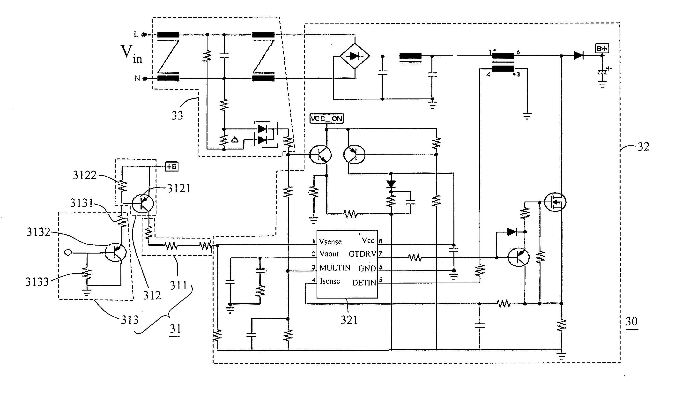
[0026] Please refer to FIG. 3, which is a schematic view showing the high-voltage detecting circuit and a partial circuit configuration of the power supply using the high-voltage detecting circuit according to a preferred embodiment of the present invention.

[0027] The power supply 30 in FIG. 3 is used to receive a AC power, convert the AC power into a first DC power with a high-voltage level and further transform the first DC power into a second DC power having a low-voltage level. The power supply 30 includes a main circuit 32 and a discharge circuit 33. Similarly, the main circuit 32 contains a PFC IC 321.

[0028] The present invention is characterized by providing a high-voltage detecting circuit 31 in connection with the high-voltage detecting terminal of the main circuit 32. The high-voltage detecting circuit 32 is composed of a high-voltage detecting module 311, a switch module 312 and a control module 313.

[0029] The high-voltage detecting module 311 functions to detect a hig...


PUM


Abstract

A high-voltage detecting circuit for saving power in a standby mode is provided. The high-voltage detecting circuit includes a high-voltage detecting module, a switch module and a control module. The high-voltage detecting module is composed of several resistors for detecting a high-voltage power supply. A control terminal of the control module is controlled by the power supply to switch off the switch module when the power supply stays at the standby mode, ensuring that the power loss of the high-voltage detecting module is eliminated.

Description

FIELD OF THE INVENTION [0001] The present invention relates to a high-voltage detecting circuit for detecting a high-voltage power supply, and more particularly to a high-voltage detecting circuit for saving power in a standby mode. BACKGROUND OF THE INVENTION [0002] By and large, a power supply utilizes an AC / DC converter to receive the commercial AC power and transforms the AC power to a DC power with a high-voltage level. Subsequently, a DC / DC converter is used to convert the DC power with a high-voltage level into a DC power with a low-voltage level for operating an electronic device, for example a desktop computer or a notebook computer. [0003] Part of the circuit layout of the conventional power supply is as shown in FIG. 1. In FIG. 1 the power supply 10 is composed of a main circuit 11, a discharge circuit 12 and a high-voltage detecting circuit 13. The main circuit 11 contains a PFC IC 111. The high-voltage detecting circuit 13 functions to detect a high-voltage power supply...

Claims


Application Information

Patent Timeline
IPC IPC(8): H02M7/217
CPCH02M3/156H02M2001/0032Y02B70/16Y02B70/10H02M1/0032
Inventor CHANG, SHIH-HSIEN
Owner DELTA ELECTRONICS INC
Learn More