System and method for modifying button functionality

a button and functionality technology, applied in the field of system and method for modifying button functionality, can solve the problems of limiting the variety of products being manufactured, lack of customizability of small electronic devices, and increasing complexity of electronic devices (like digital watches), so as to improve the user experience, improve the construction and methodology, and customize the functionality and configuration of the devi

Inactive Publication Date: 2007-04-12
TIMEX GROUP
View PDF4 Cites 3 Cited by
  • Summary
  • Abstract
  • Description
  • Claims
  • Application Information

AI Technical Summary

Benefits of technology

[0013] Accordingly, it is an object of the present invention to provide an improved construction and methodology for an electronic device and, in particular, for a wristwatch, that allows a user to more particularly customize the functionality and configuration of the device.
[0014] It is another object and advantage of this invention to provide an improved construction and methodology for an electronic device and, in particular, for a wristwatch, that makes the device more “user friendly” to the user.
[0015] It is yet another object and advantage of this invention to provide an improved mode display methodology that makes the device more marketable to a wider range of users.
[0016] It is still another object and advantage of this invention to provide an improved construction and methodology for an electronic device and, in particular, for a wristwatch, that permits manufacturers, designers or programmers of such devices to further provide users with demanded functionality, yet provide a construction and methodology to permit the electronic device to be configured to better meet the users needs, desires and uses therefor.
[0017] It is a further object of the present invention to provide a multimode device that can provide additional mode capability and functionality.
[0018] Another object of the present invention is to provide a device having an improved multi-level user interface.

Problems solved by technology

One perceived problem in the art today is the fact that certain electronic devices, such as digital watches as but one example, are designed with a particular configuration.
Another but somewhat related perceived problem in the art today is a lack of customizability of small electronic devices such as, but not limited to timepieces, and wristwatches in particular.
For example, with the advancement of technology, such electronic devices (like digital watches) are becoming more powerful and increasingly complex, and manufacturers are trying to capitalize on this advancement by increasing the functionally of such products while actually limiting the variety of products being manufactured.
However, to date, there is a perception that all that is being accomplished is the manufacture of products having advanced functionality not being appreciated by the novice and or intermediate users.

Method used


Image

  • System and method for modifying button functionality
  • System and method for modifying button functionality
  • System and method for modifying button functionality

Examples


first embodiment

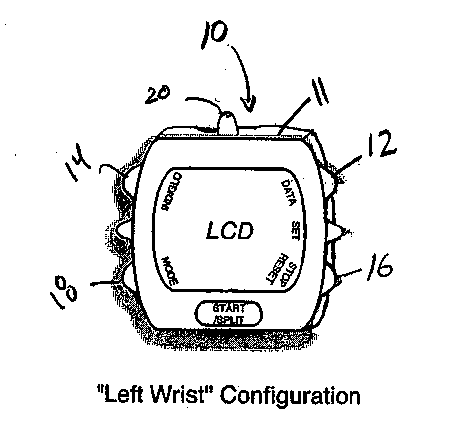
[0028] As indicated above, the button layout for a device (e.g. and in particular, a digital watch) is typically fixed and the function for each of the buttons is determined during the development of the watch. More often than not the watch is designed so that the button placement favors those who wear the watch on the left wrist and operate it with the right hand, which leads to an undesirability if the wearer wishes to wear the watch on the right wrist, as the button layout then becomes less than optimal, and operating the watch is cumbersome. The present invention, in accordance with a first embodiment, aims to allow the user to wear the watch on either wrist and enjoy the ease of use intended by the manufacturer.

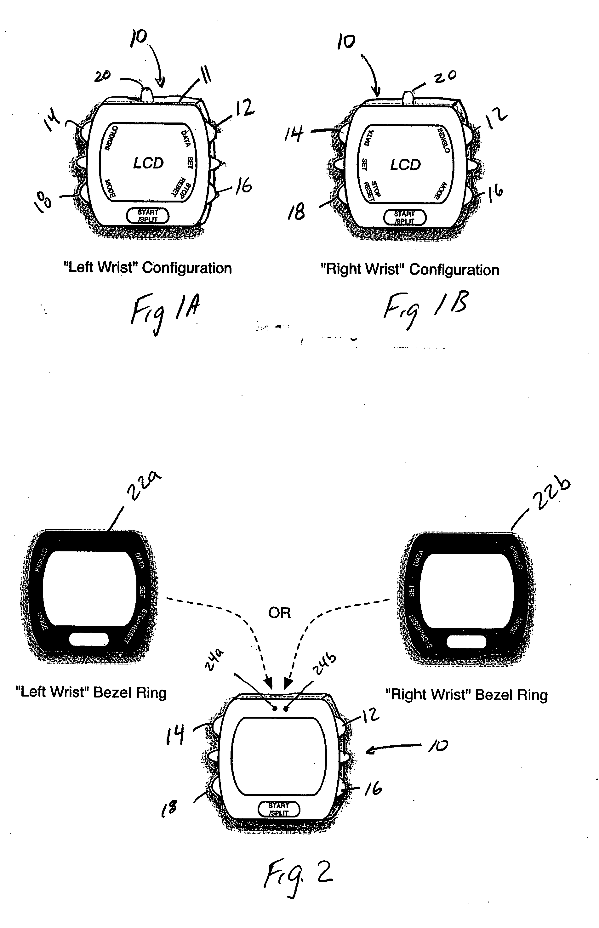
[0029] Therefore, reference is first made to FIG. 1, which generally illustrates a first implementation of the first embodiment of the present invention. In this software configuration implementation, the button functions may be indicated by text in the LCD, similar to t...

second embodiment

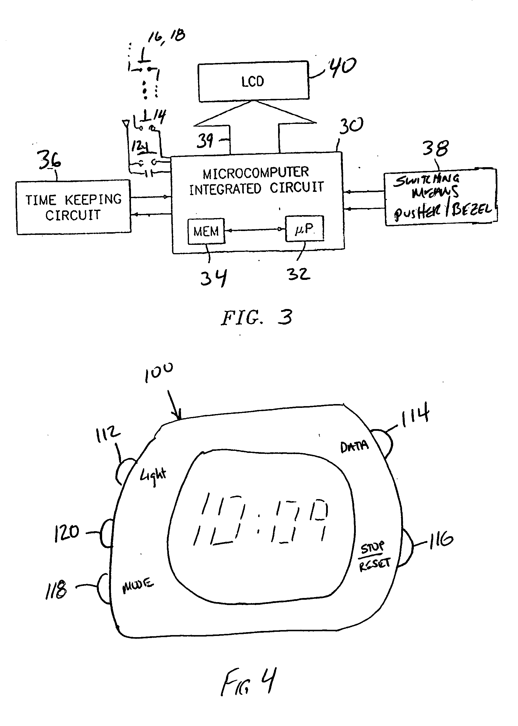
[0054] Thus to the extent necessary, the circuit of FIG. 3 is likewise applicable to the second embodiment set forth in FIG. 4.

[0055] It can thus be seen that the present invention provides an improvement in functionality over prior art multimode electronic devices and, in particular, in a wristwatch, that allows the electronic device to customize itself to the use, desires and capabilities of the user. Further, by implementing the present invention, an improved construction and methodology for such electronic devices that makes the device more “user friendly” and customizable to the user is provided. Still further, the present invention provides a user interface and improved functionality that makes the device more marketable to a wider range of users. Lastly (but not exhaustively), the present invention permits manufacturers, designers or programmers of such devices to further provide users with demanded functionality, yet provide a construction and methodology to permit the elect...


PUM


Abstract

An electronic device comprising a first pusher located in a first position on the electronic device, wherein actuation of the first pusher causes initiation of a first operational sequence; a second pusher located in a second position on the electronic device, wherein actuation of the second pusher causes initiation of a second operational sequence; an integrated circuit, operatively coupled to the first and second pushers, for selectively carrying out the first and second operational sequences; switching means for switching the operational sequences initiated by the first and second pushers such that subsequent to actuation of the switching means, the first pusher causes initiation of the second operational sequence and the second pusher causes initiation of the first operational sequence; whereby the first operational sequence is different from the second operational sequence.

Description

RELATED APPLICATIONS [0001] This application claims the benefit of U.S. Provisional Application No. 60 / 725,792, filed Oct. 12, 2005.BACKGROUND OF THE INVENTION [0002] The present invention is directed to a system and method for modifying and / or altering the functionality of one or more buttons or pushers on an electronic device, wherein the electronic device is preferably a timepiece and a wristwatch in particular. [0003] One perceived problem in the art today is the fact that certain electronic devices, such as digital watches as but one example, are designed with a particular configuration. For example, in a typical digital timepiece such as that described in U.S. Pat. No. 6,420,959, the functionality associated with particular buttons / pushers is non-changeable. [0004] By that it is meant, for example and as it relates to U.S. Pat. No. 6,420,959, that the S1 button is associated with the backlighting and the S3 button is the mode selector, and such functionality associated with ea...

Claims


Application Information

Patent Timeline
Patent Type & Authority Applications(United States)
IPC IPC(8): G04C21/00G04C17/00
CPCG04G21/00G04G21/08
Inventor CIERVO, RICHARD D.
Owner TIMEX GROUP
Why Eureka
Try Eureka