Method for controlling redundancy and transmission device using the same

a transmission device and redundancy technology, applied in the field of redundancy control and transmission device, can solve the problems of reducing available bandwidth, temporary signal interruption, and huge infrastructure of sonet communications network, so as to and prevent the reduction of available bandwidth

Active Publication Date: 2007-04-12
FUJITSU LTD
View PDF5 Cites 13 Cited by
  • Summary
  • Abstract
  • Description
  • Claims
  • Application Information

AI Technical Summary

Benefits of technology

[0018] According to one aspect of the present invention, there is provided a redundancy controlling method and a transmission device using the same, capable of preventing reduction of available bandwidth and temporary signal interruption due to unwanted activation of an RPR redundancy function.
[0019] According to another aspect of the present invention, there is provided a redundancy controlling method for controlling a first redundancy function that switches between a working line and a protection line in response to a detection of a line error and a second redundancy function that performs a path switching in response to a detection of a path error in a ring network operating at a path rate lower than a line rate thereof, the method comprising a step of masking the path error detection within a period from a time of the detection of the line error to an expected time of the detection of the path error. This method makes it possible to prevent reduction of available bandwidth and temporary signal interruption due to unwanted activation of the second redundancy function.
[0020] It is preferable that the redundancy controlling method described above further comprise a step of stopping masking the path error detection so as to enable the second redundancy function if a line error is detected on the protection line after the switching by the first redundancy function from the working line to the protection line. This method makes it possible to handle the double errors on the working line and the protection line, i.e., a double failure, using the second redundancy function.
[0021] According to still another aspect of the present invention, there is provided a transmission device for use in a ring network operating at a path rate lower than a line rate thereof, having a first redundancy function that switches between a working line and a protection line in response to a detection of a line error, and a second redundancy function that performs a path switching in response to a detection of path error. The transmission device comprises a line error detecting unit that detects the line error on the working line and on the protection line, a switching unit that enables the first redundancy function so as to switch from the working line to the protection line in response to the detection of the line error on the working line, a path error detecting unit that detects a path error in a signal output from the switching unit, and a masking unit that masks the path error detection by the path error detecting unit within a period from a time of the detection of the line error on the working line by the line error detecting unit to an expected time of the detection of the path error by the path error detecting unit. This transmission device can prevent reduction of available bandwidth and temporary signal interruption due to unwanted activation of the second redundancy function.
[0022] In the above transmission device, it is preferable that the masking unit mask the path error detection by the path error detecting unit within a period from a start time of the switching to an expected time of the detection of the path error by the path error detecting unit when the switching unit switches back from the protection line to the working line. With this configuration, the transmission device can prevent reduction of available bandwidth and temporary signal interruption due to unwanted activation of the second redundancy function during the switchback.

Problems solved by technology

The existing infrastructure for the SONET communications networks is huge.
However, if the RPR ring network is formed with use of the existing SONET infrastructure as a physical layer, both the SONET redundancy function and the RPR redundancy function are activated in the event of failure, resulting in a conflict.
Moreover, the unwanted activation of the RPR redundancy function causes a temporary signal interruption.
As described above, although a path failure is recovered from by the SONET redundancy operation, the unwanted activation of the RPR redundancy function causes reduction of available bandwidth and temporary interruption of signals.
With this method, however, activation of the RPR redundancy function with the increased delay is applied even when RPR redundancy is really needed.

Method used


Image

  • Method for controlling redundancy and transmission device using the same
  • Method for controlling redundancy and transmission device using the same
  • Method for controlling redundancy and transmission device using the same

Examples


Embodiment Construction

[0037] The following description provides exemplary embodiments of the present invention with reference to the accompanying drawings.

[0038]

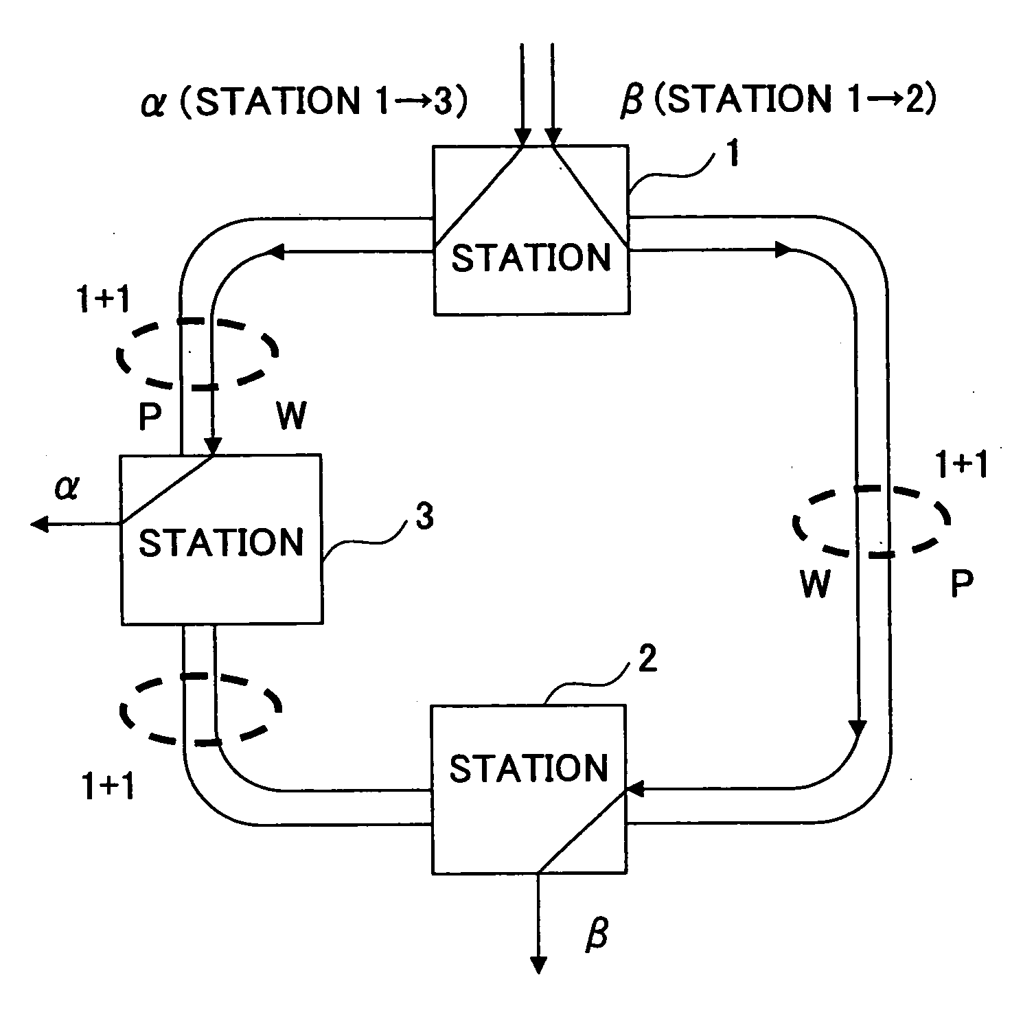
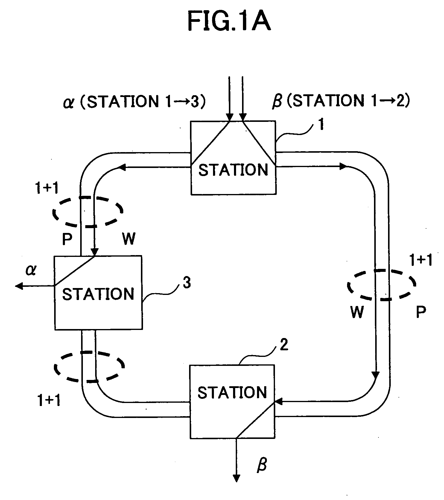
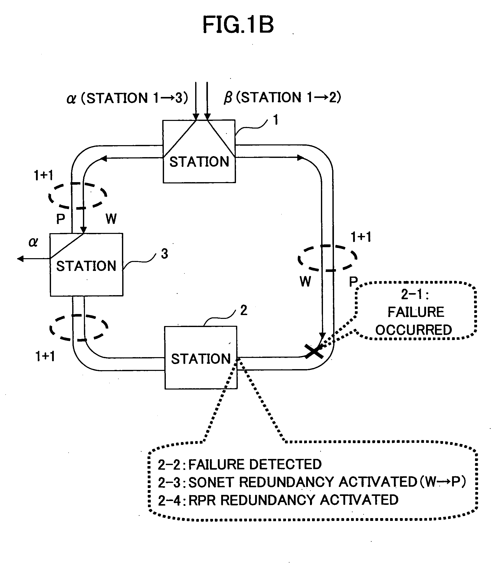
[0039]FIG. 3 illustrates a configuration of an RPR over SONET network according to an embodiment of the present invention. Stations 10, 20, and 30 forming the network are SONET devices. The stations 10 and 20 are interconnected through a working (W) line 40 and a protection (P) line 41. The stations 20 and 30 are interconnected through a working (W) line 42 and a protection (P) line 43. The stations 30 and 10 are interconnected through a working (W) line 44 and a protection (P) line 45. The working (W) lines 40, 42, and 44 and the protection (P) lines 41, 43, and 45 are made of optical fibers.

[0040] The stations 10, 20, and 30 have the same configuration. The station 10 comprises optical interface sections 11-14, a switch section 15, an RPR section 16, and a CPU section 17.

[0041] The optical interface sections 11 and 12 are connected to the wo...


PUM


Abstract

A redundancy control method is disclosed that controls a first redundancy function that switches between a working line and a protection line in response to a detection of a line error and a second redundancy function that performs a path switching in response to a detection of a path error in a ring network operating at a path rate lower than a line rate thereof. The method comprises a step of masking the path error detection within a period from a time of the detection of the line error to an expected time of the detection of the path error.

Description

BACKGROUND OF THE INVENTION [0001] 1. Field of the Invention [0002] The present invention generally relates to a method for controlling redundancy and a transmission device, and particularly relates to a method for controlling redundancy and a transmission device for use in a ring network operating at a path rate lower than a line rate thereof. [0003] 2. Description of the Related Art [0004] In recent years, there has been a growing demand for IP networks with greater reliability. RPR (Resilient Packet Ring) having a ring switching function for LAN (the term “LAN” as used herein includes WAN and MAN as well as LAN) is one promising technology to improve the reliability of the IP networks. In RPR networks, Ethernet (TM) frames are encapsulated in RPR frames. The RPR redundancy employs a steering method and a wrapping method, which are standardized in IEEE 802.17. Path failure information is transmitted between stations using control frames, thereby achieving reliability close to that...

Claims


Application Information

Patent Timeline
Patent Type & Authority Applications(United States)
IPC IPC(8): H04J1/16H04J3/14H04L12/26G08C15/00G01R31/08G06F11/00H04L1/00
CPCH04J3/085H04J2203/0042H04J2203/006H04L1/22H04L12/42
Inventor FUJIMORI, TOMOYOSHISAITOH, SATORUHONMA, HIROYUKI
Owner FUJITSU LTD
Why Eureka
Try Eureka