Seamless capsule manufacturing method, seamless capsule manufacturing device and seamless capsule

Inactive Publication Date: 2007-04-12
FREUNT IND
View PDF15 Cites 10 Cited by
  • Summary
  • Abstract
  • Description
  • Claims
  • Application Information

AI Technical Summary

Benefits of technology

[0023] With a seamless capsule manufacturing method according to the present invention, liquid drops are ejected from a nozzle into hardening liquid. Then, as the flow rate of hardening liquid is changed while the liquid drops are still held in a sol state, the ejected liquid drops are deformed as a function of the change in the flow rate and turned to nonspherical liquid drops. Neither a narrow tube nor a mold having a diameter smaller than the diameter of the ejected spherical liquid drops is used to deform the liquid drops and simply the flow rate of hardening liquid is changed in the molding process. Therefore, the tube or the like is prevented from being clogged and the flow of hardening liquid is prevented from being pulsated to consequently improve the quality of produced capsules and the productivity of manufacturing capsules.
[0024] Since a seamless capsule manufacturing device according to the present invention comprises a n

Problems solved by technology

However, the above-cited known methods of manufacturing nonspherical capsules are accompanied by the following problems.
Firstly, with the method of Patent Document 3, the cooling flow for forming a recess on each liquid drop requires a very delicate operation of adjusting the cooling flow for forming a recess on a liquid drop and it is very difficult to regulate the cutting flow and the recess forming flow to an optimal condition.
Additionally, the cooling flow has to be adjusted each time the capsule size is or the capsule ingredients are changed to entail a cumbersome adjusting operation.
Next, the methods of Patent Documents 1, 2 and 4 involve a problem that the narrow tube and the mold for forming deformed nonspherical capsules can easily bec

Method used


Image

  • Seamless capsule manufacturing method, seamless capsule manufacturing device and seamless capsule
  • Seamless capsule manufacturing method, seamless capsule manufacturing device and seamless capsule
  • Seamless capsule manufacturing method, seamless capsule manufacturing device and seamless capsule

Examples


example 1

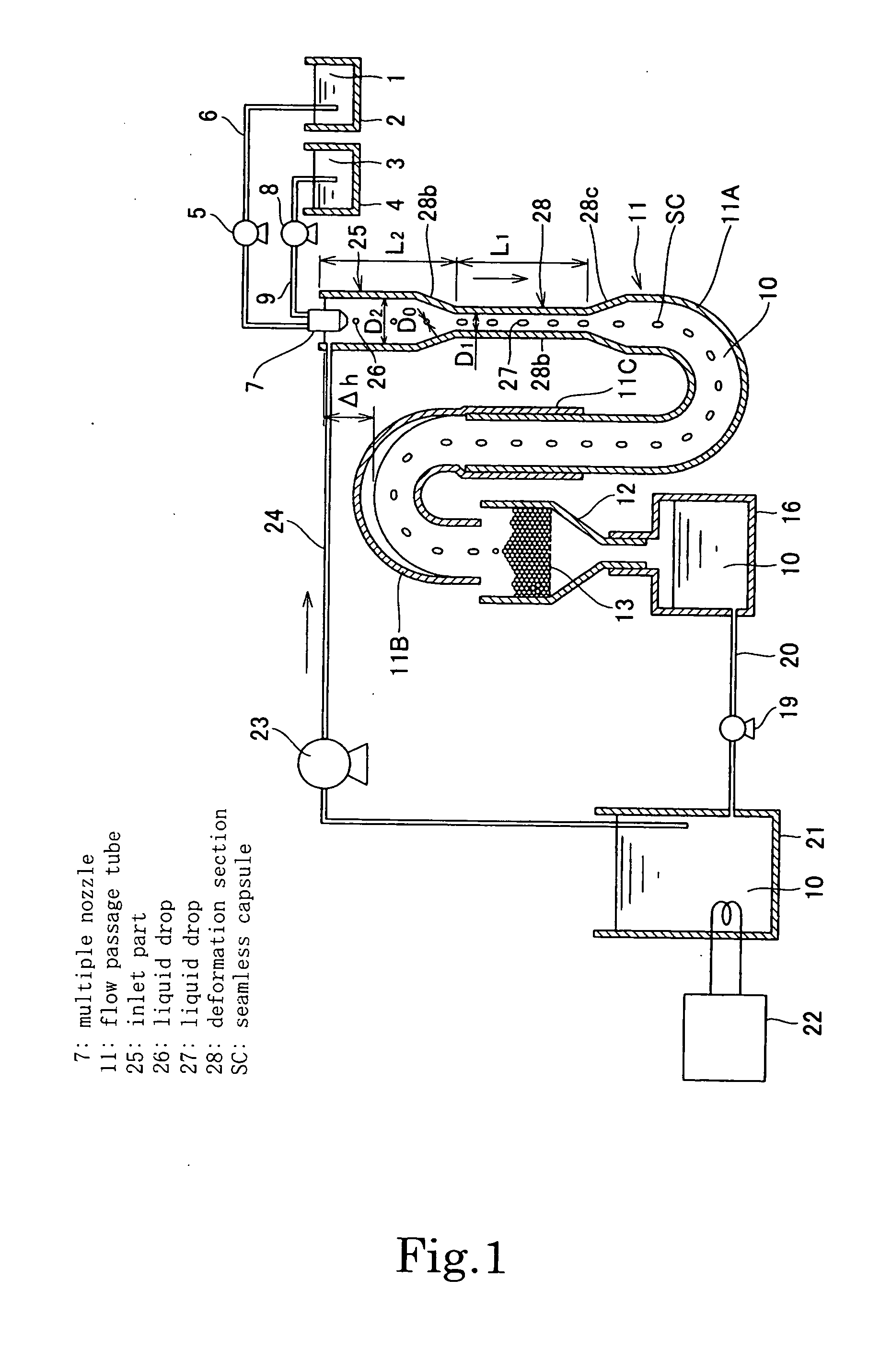
[0093] A filling liquid (core liquid) of medium-chain triglyceride (to be referred to as MCT hereinafter) as shown in Table 1 below was prepared. At the same time, a film forming liquid was prepared by heating and dissolving a mixture of the ingredients listed in Table 2 below at a mixing ratio also listed in Table 2. Then, conical deformed capsules were manufactured by means of a seamless capsule manufacturing device as illustrated in FIG. 1. The values of the parameters as listed in Table 3 below were used for the manufacture of the seamless capsules. The coat film ratio in Table 3 refers to the ratio of the mass of the coat film of a seamless capsule relative to the total mass of the seamless capsule.

TABLE 1Core liquid compositionMCT100total100

(wt %)

[0094]

TABLE 2Film forming liquid compositiongelatin27glycerin3water70total100

(wt %)

[0095]

TABLE 3Encapsulation parametersExample 1Example 2Example 3liquid drop diameter5.77.95.7during manufacture D0(mm)number of produced6315capsule...

example 2

[0096] Core liquid and film forming liquid were prepared with the mixing ratios listed respectively in Tables 1 and 2 as in Example 1 and deformed capsules showing an echinus-shaped profile were manufactured by means of a seamless capsule manufacturing device as illustrated in FIG. 1. The values of the parameters as listed in Table 3 below were used for the manufacture of the seamless capsules.

example 3

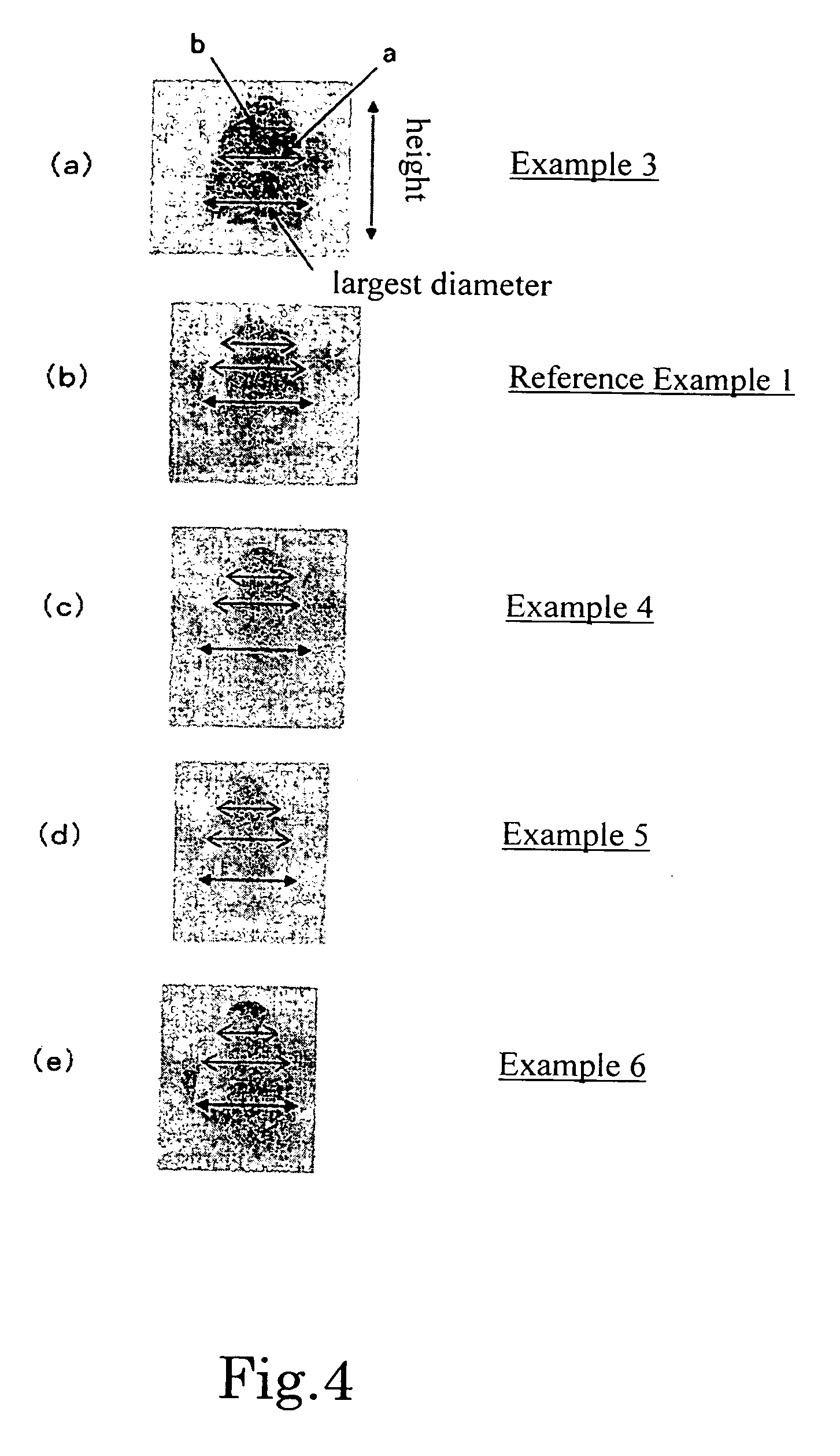
[0098] Conical deformed capsules were manufactured from a filling liquid (core liquid) as shown in Table 1 and a film forming liquid prepared by heating and dissolving a mixture of the ingredients listed in Table 2 at a mixing ratio also listed in Table 2 as in Example 1. The obtained deformed capsules were separated from hardening liquid to obtain conical deformed capsules (undried deformed capsules). The values of the parameters as listed in Table 5 below were used for the manufacture of the seamless capsules. The profile of the deformed capsules is shown in FIG. 4(a).

[0099] The largest diameter in cross sections perpendicularly intersecting the vertical direction of the conical seamless capsule and the position (height) thereof were determined, provided that the major axis of the conical seamless capsule is expressed as height (h). It may be safe to assume that the profile of the seamless capsule comes close to spherical from conical (nonspherical) as the ratio of the largest di...


PUM

PropertyMeasurementUnit
Flow rateaaaaaaaaaa
Diameteraaaaaaaaaa
Areaaaaaaaaaaa

Abstract

A seamless capsule manufacturing device comprises a multiple nozzle 7 for ejecting liquid drops into hardening liquid 10 and a flow passage tube 11 for containing hardening liquid 10. The flow passage tube 11 has a deformation section 28 that includes an inlet part 25 and a formation tube part 28b showing a cross sectional area smaller than the inlet part 25. The liquid drops ejected from the multiple nozzle 7 into the hardening liquid 10 are once made to become spherical liquid drops 26 in a sol state at the inlet part 25. The liquid drops 26b are introduced from the inlet part 25 into the deformation section 28 while they are still in a sol state. As hardening liquid 10 is introduced from the inlet part 25 into the formation tube part 28b, its flow rate is changed and the liquid drops 26 are deformed due to the change in the flow rate to produce nonspherical seamless capsules SC. With this arrangement, it is possible to provide a method and a device for manufacturing high quality nonspherical seamless capsules with an enhanced level of productivity without requiring cumbersome parameter defining operations and delicate control operations.

Description

TECHNICAL FIELD [0001] This invention relates to the technology of manufacturing seamless capsules by coating drops of a filling substance such as food, dietary food, medicine, aromatic or spice with a film containing gelatin or agar. More specifically, the invention relates to a method of manufacturing nonspherical seamless capsules. BACKGROUND ART [0002] Conventionally, many seamless capsules for use in the field of medicines and so on are manufactured by means of a so-called dropping method. A multiple nozzle is used for the dropping method. Thus, in the case of manufacturing two-layered capsules, a double nozzle having an ejection port for ejecting the capsule filling substance and an ejection port for ejecting the film forming substance respectively arranged at the inside and at the outside is used. The filling substance and the film forming substance are ejected from the tips of the respective nozzles into hardening liquid and the ejected liquid drops take a spherical form due...

Claims


Application Information

Patent Timeline
IPC IPC(8): A61K9/48B01J13/04A61J3/07A61K47/42B01J2/06
CPCA61J3/07A61K9/48B01J2/06B01J13/04
Inventor YAMANAKA, KUNIAKIUNOSAWA, KAZUOMITAKEI, NARIMICHIKONNO, SHOUJIIKEDA, MASAYUKI
Owner FREUNT IND
Why Eureka
Try Eureka