

Photoresist coating apparatus, medium, and method efficiently spraying photoresist
- Summary
- Abstract
- Description
- Claims
- Application Information
AI Technical Summary
Benefits of technology
Problems solved by technology
Method used
Image

Examples
Embodiment Construction
[0040] Reference will now be made in detail to embodiments of the present invention, examples of which are illustrated in the accompanying drawings, wherein like reference numerals refer to the like elements throughout. Embodiments are described below to explain the present invention by referring to the figures.
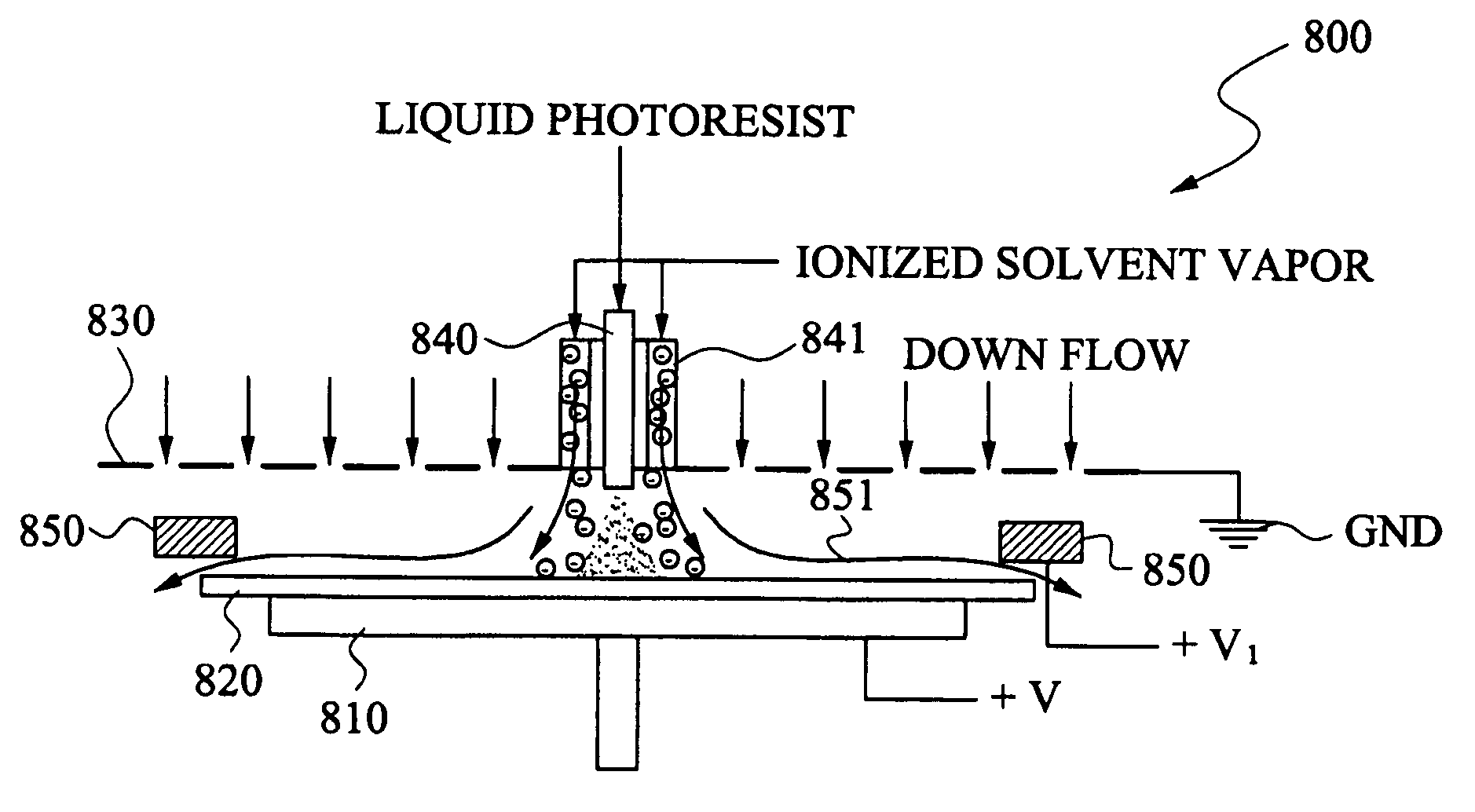
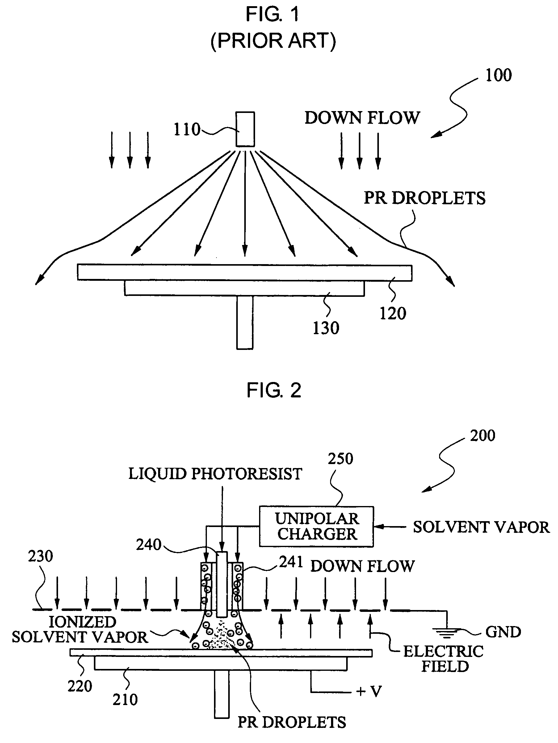
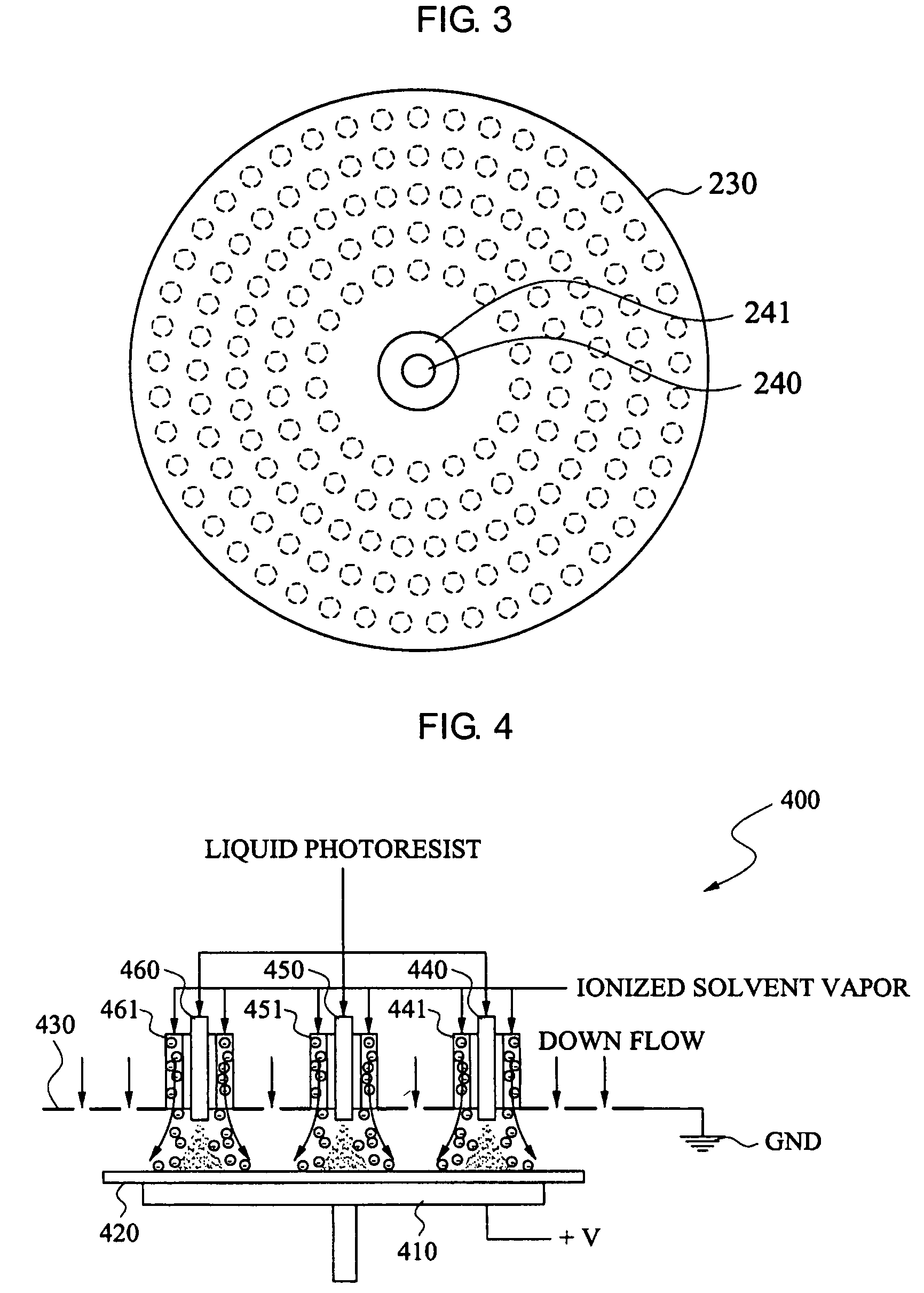
[0041]FIG. 2 illustrates a photoresist coating apparatus 200, according to an embodiment of the present invention. Referring to FIG. 2, the photoresist coating apparatus 200 may include a holder 210, a plate 230, a vapor inducing pipe 241 to supply an ionized solvent vapor, a spray nozzle 240, and a unipolar charger 250, for example. The vapor inducing pipe 241 corresponds to a vapor dispenser. The spray nozzle 240 corresponds to a photoresist dispenser.
[0042] The holder 210 may be used to hold a substrate 220, such as a semiconductor wafer or a glass substrate, in a photoresist coating process. The substrate 220 may be fixed, e.g., using a vacuum pump (not illustrated) so ...
PUM
 Abstract
Description
Claims
Application Information