Slip joint for use in steering system

a steering system and slip joint technology, applied in the direction of slip couplings, couplings, transportation and packaging, etc., can solve the problems of discomfort and vibration of the driver, and the steering system transmits vibration and noise to the driver, so as to improve the steering precision, reduce noise and vibration, and facilitate fabrication

Inactive Publication Date: 2007-04-12
HL MANDO CORP
View PDF2 Cites 5 Cited by
  • Summary
  • Abstract
  • Description
  • Claims
  • Application Information

AI Technical Summary

Benefits of technology

[0020] Accordingly, the present invention has been made to solve the above-mentioned problems occurring in the prior art, and an object of the present invention is to provide a slip joint for a steering system, which can reduce noise and vibration, improve steering precision, and guarantee easy fabrication by modifying the characteristics of a spring pin for reducing the clearance between a pipe and a shaft, which constitute the slip joint in a universal joint.

Problems solved by technology

As a result, vibration and noise are transmitted from the steering system to the driver, who operates the steering wheel, and discomfort him.

Method used


Image

  • Slip joint for use in steering system
  • Slip joint for use in steering system
  • Slip joint for use in steering system

Examples


first embodiment

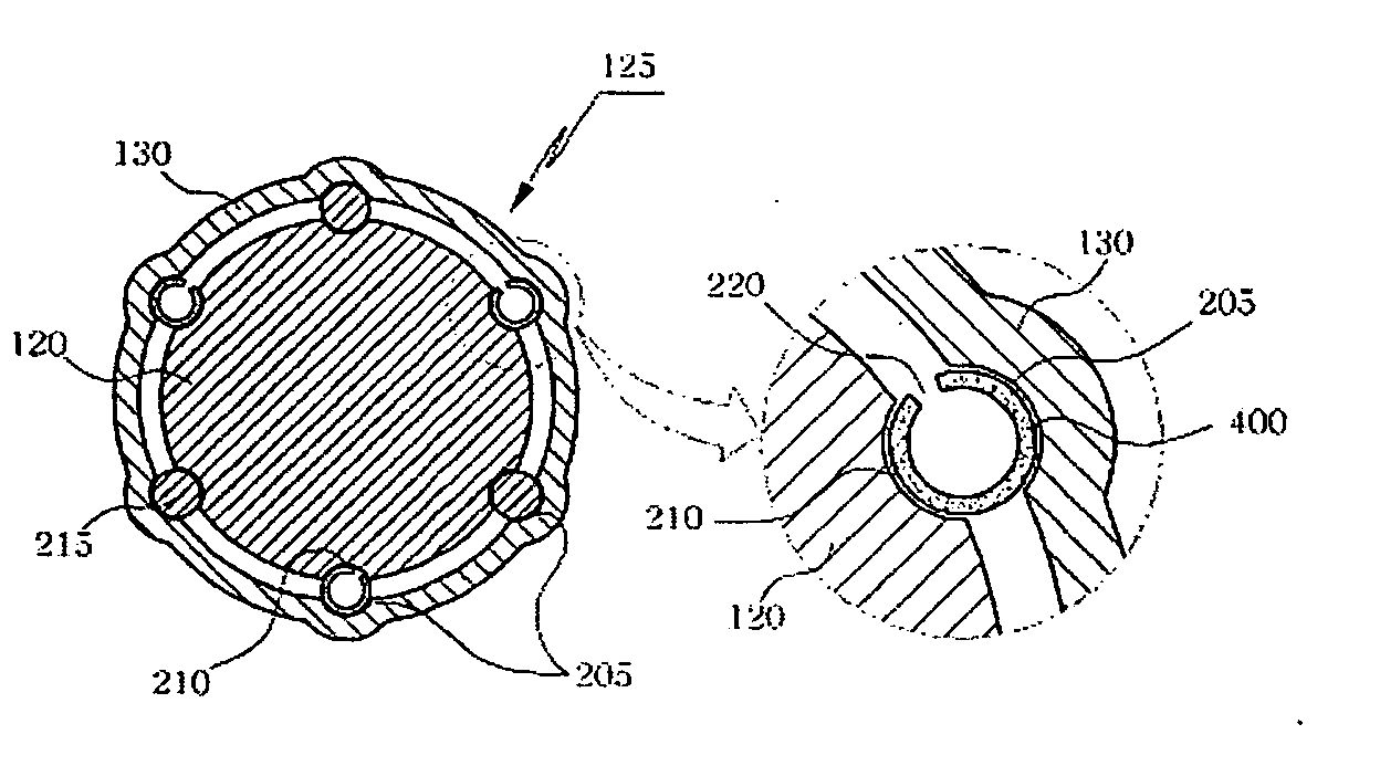
[0035]FIG. 4 is a sectional view showing a slip joint according to the present invention. The slip joint includes a shaft 120, a pipe 130, shaft grooves 210, pipe grooves 205, pins 215, and second spring pins 400.

[0036] As shown, the shaft 120 has shaft grooves 210 formed on its outer peripheral surface, and the pipe 130 has pipe grooves 205 formed on its inner peripheral surface. The pipe grooves 205 and the shaft grooves 210 extend in the longitudinal direction of the slip joint. Respective shaft grooves 210 are coupled to corresponding pipe grooves 205 while facing each other so that cylindrical spaces are defined between them.

[0037] According to the present embodiment, six cylindrical spaces are positioned at an angular interval of 60°. As shown, a pin 215 is inserted into one of a pair of cylindrical spaces, which face each other, and a second spring pin 400 is inserted into the other.

[0038] The pins 215 have the shape of rods and guarantee transmission of rotational force fr...

second embodiment

[0043]FIG. 5 is a sectional view showing a slip joint according to the present invention. The slip joint includes a shaft 120, a pipe 130, pipe grooves 205, shaft grooves 210, pins 215, second spring pins 400, and third spring pins 500.

[0044] The second spring pins 400 are made of a plastic material, which has weaker elastic restoration force than metal. Therefore, metallic third spring pins 500 are positioned on the inner peripheral surface of the second spring pins 400, respectively. The third spring pins 500 have a continuous seam and can enlarge towards the outer peripheral surface (i.e. the inner diameter increases) or contract towards the inner peripheral surface (i.e. the inner diameter decreases).

[0045] When the third spring pins 500 are to be positioned on the inner peripheral surface of the second spring pins 400, the inner diameter of the third spring pins 500 is reduced. After positioning, the elastic force of the third spring pins 500 enlarges the second spring pins 40...

third embodiment

[0046]FIG. 6 is a sectional view showing a slip joint according to the present invention. The slip joint includes a shaft 120, a pipe 130, pipe grooves 205, shaft grooves 210, pins 215, second spring pins 400, third spring pins 500, and a connector 600.

[0047] The connector 600 connects the pins 215 to the second spring pins 400. According to the present embodiment, three pairs of pins 215 and three pairs of third spring pins 500 (i.e. a total of six separate components) are configured as an integral unit, which is hereinafter referred to as a slipper 700. This simplifies the assembly process.

[0048]FIG. 7 is a perspective view partially showing a slip joint according to the third embodiment of the present invention. The slip joint includes pins 215, second spring pins 400, third spring pins 500, and a connector 600.

[0049] As shown, the connector 600 connects one side of the second spring pins 400 to one side of the pins 215 and extends along the outer peripheral surface of the shaf...


PUM


Abstract

Disclosed is a slip joint including a shaft having a plurality of shaft grooves formed on an outer peripheral surface in the longitudinal direction; a pipe having pipe grooves formed on an inner peripheral surface, the pipe grooves facing the shaft grooves so as to define cylindrical spaces, an end of the shaft being inserted into the pipe; a pin inserted into one of the cylindrical spaces; a first spring pin inserted into a different one of the cylindrical spaces, the first spring pin being made of a cylindrical elastic body having a longitudinal seam; a second spring pin inserted into the first spring pin, the second spring pin being made of an elastic body; and a connector for integrally connecting the first spring pin to the pin so as to constitute a slipper.

Description

RELATED APPLICATION [0001] This application claims convention priority to Korean patent application No. 2005-0094998 filed on Oct. 10, 2005, the content of which is incorporated by reference. [0002] 1. Field of the Invention [0003] The present invention relates to a slip joint for a steering system. More particularly, the present invention relates to a slip joint for a steering system, which can reduce noise and vibration, improve steering precision, and guarantee easy fabrication by modifying the characteristics of a spring pin for reducing the clearance between a pipe and a shaft, which constitute the slip joint in a universal joint. [0004] 2. Description of the Prior Art [0005] As generally known in the art, an automobile is provided with various devices in order to improve the safety and aid convenient driving. For example, a steering system is used to alter the direction of the automobile as desired by rotating a steering wheel. Particularly, the steering system changes the cen...

Claims


Application Information

Patent Timeline
Patent Type & Authority Applications(United States)
IPC IPC(8): F16D7/00
CPCB62D1/16B62D1/20F16D3/06F16C2326/24F16C29/02F16C3/035F16D3/20F16C3/03
Inventor PARK, JUNG SIK
Owner HL MANDO CORP
Why Eureka
Try Eureka