

Wireless Communication Terminal, Transmission Control Mehtod, and Computer Program
- Summary
- Abstract
- Description
- Claims
- Application Information
AI Technical Summary
Benefits of technology
Problems solved by technology
Method used
Image

Examples
first embodiment
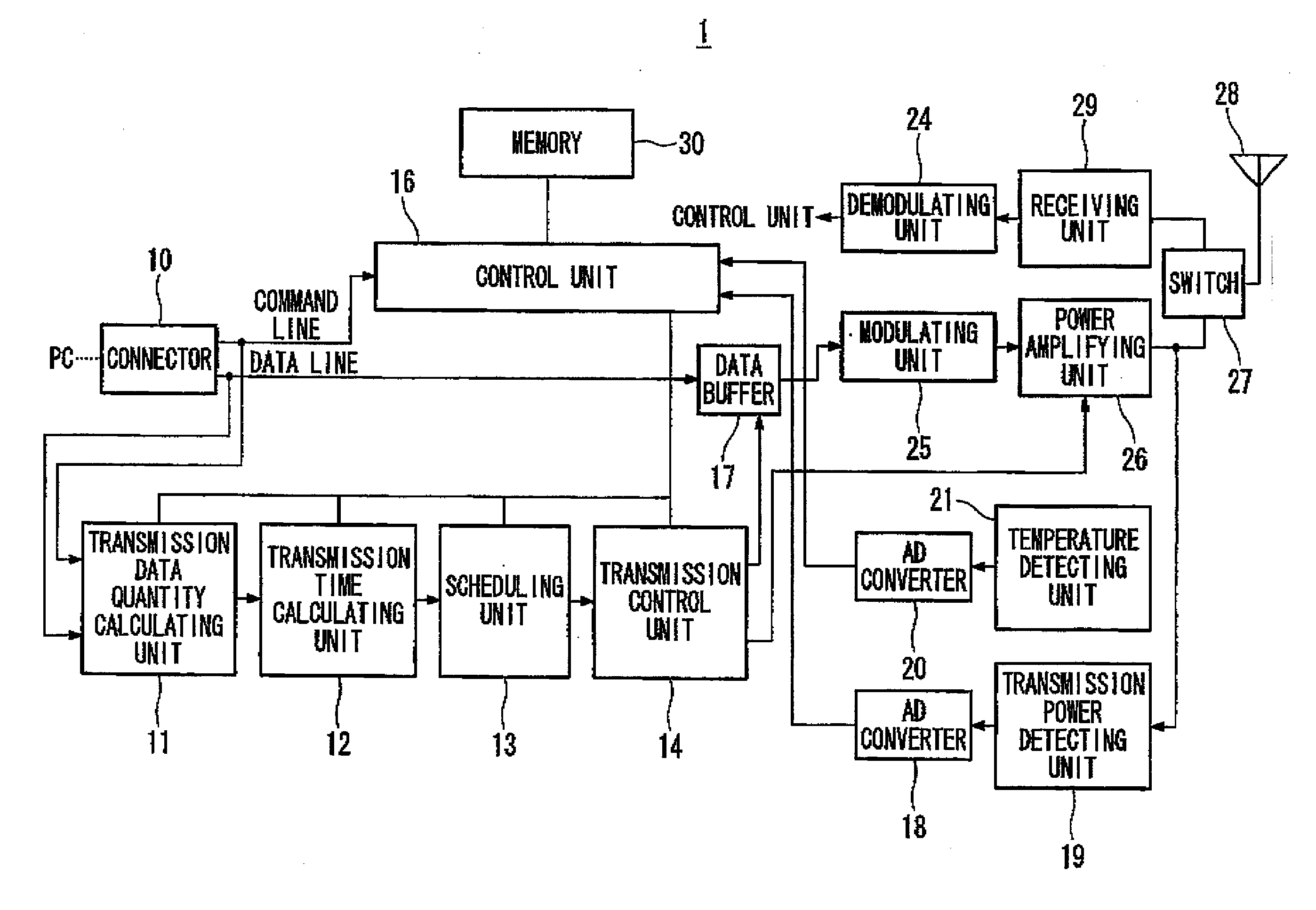
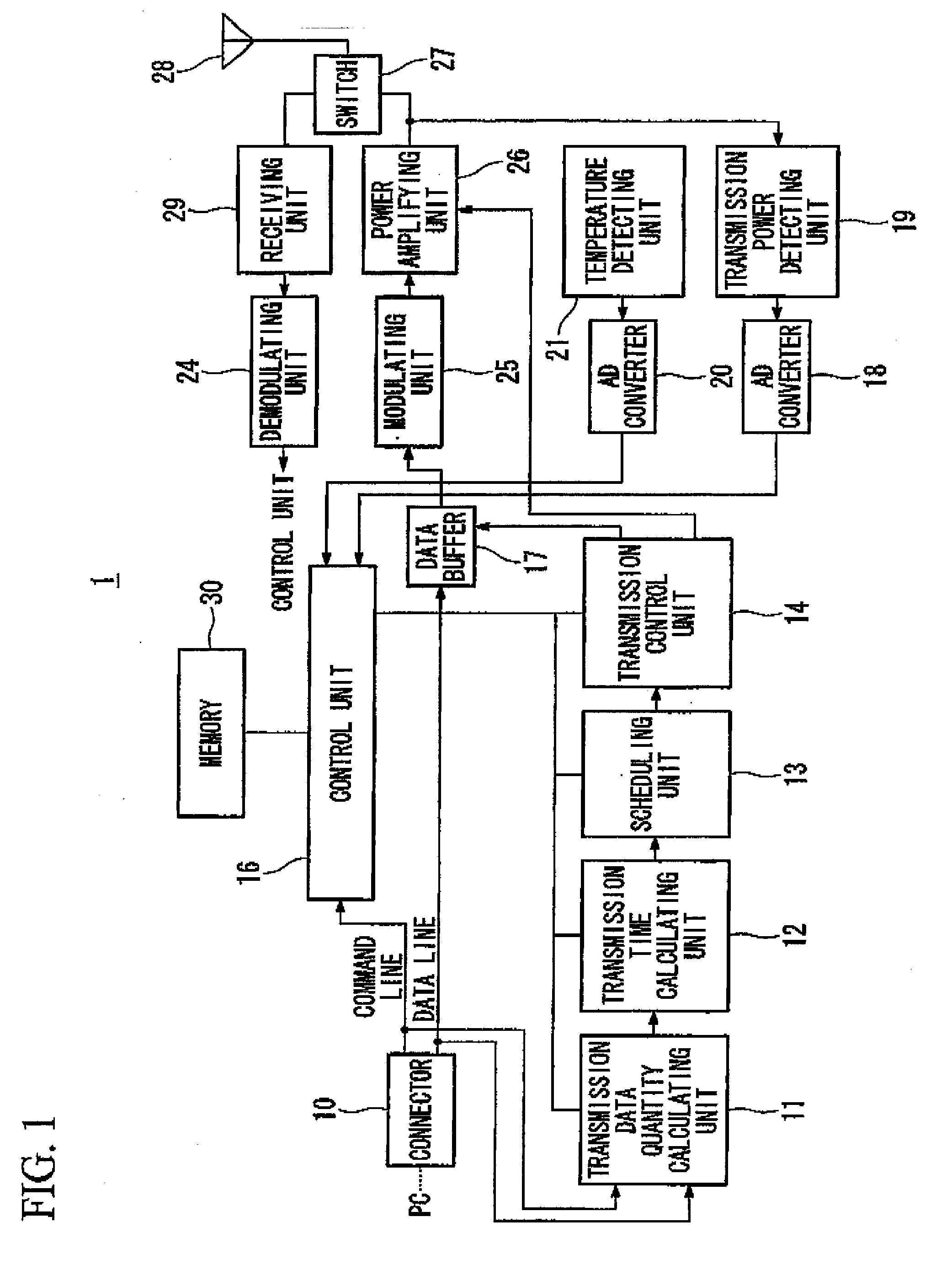
[0078]FIG. 1 is a schematic block diagram illustrating a wireless communication terminal in accordance with a first embodiment of the present invention. A wireless communication terminal 1 can be, but is not limited to, a card wireless communication device that is inserted into a card slot of a PC (Personal Computer). The wireless communication terminal 1 may include an antenna 28 that is configured to transmit and / or receive a radio wave to or from a wireless base station. The wireless base station is not illustrated. The wireless communication terminal 1 may include a switch 27 that is configured to switch the transmission mode and the receiving mode as the operating mode of the wireless communication terminal 1. The switch 27 is connected to the antenna 28.
[0079] The wireless communication terminal 1 may include a receiving unit 29 and a power amplifying unit 26. The switch 27 is also connected to the receiving unit 29 and the power amplifying unit 26. When the switch 27 receive...
second embodiment
[0210] In accordance with the above-described first embodiment, the transmission start and discontinuation are repeated for transmitting divided frames of data so as to maintain the terminal temperature below the upper limit of the operation guarantee temperature range.
[0211] In accordance with the second embodiment, a transmission of data traffic only is discontinued instead of discontinuing the transmission, while a transmission of control traffic is continued to ensure the establishment of communication between the wireless base station and the wireless communication terminal.
[0212]FIG. 17 is a block diagram illustrating a data traffic structure in the CDMA 1×EV-DO communication system. The data traffic is of a Data 56. Thus, only the transmission of the Data 56 is discontinued, while continuing the transmissions of a control traffic 60 that includes Pilot 61, Medium Access Control 62, Ack 63, Reverse Rate Inductor 64, and Data Rate Control 65. If the transmission of Pilot 61 i...
third embodiment
[0215] In accordance with the second embodiment, the data traffic is not transmitted to reduce the mission power. In accordance with CDMA 1×EV-DO communication system, the transmission rate is changeable. In accordance with the third embodiment, the wireless communication terminal is configured to reduce the transmission rate,
[0216]FIG. 20 is a diagram illustrating interrelationships between transmission rates and transmission powers in accordance with CDMA 1×EV-DO communication system. Reducing the data rate (Data Rate) reduces the gain of the transmission power. “DataOffsetNorm”, “DataOffset9k6”, “DataOffset76k8”, and “DataOffset153k6” are the values that are transmitted from the wireless base station.
[0217]FIG. 21 is a diagram illustrating variations in terminal temperature over time when the transmission is performed without reducing the transmission rate. FIG. 22 is a diagram illustrating variations in terminal temperature over time when the transmission is performed with red...
PUM
 Abstract
Description
Claims
Application Information