
Automation and Control of Energy Efficient Fluid Catalytic Cracking Processes for Maximizing Value Added Products

Inactive Publication Date: 2009-04-16
SAUDI ARABIAN OIL CO
View PDF42 Cites 20 Cited by
  • Summary
  • Abstract
  • Description
  • Claims
  • Application Information

AI Technical Summary

Benefits of technology

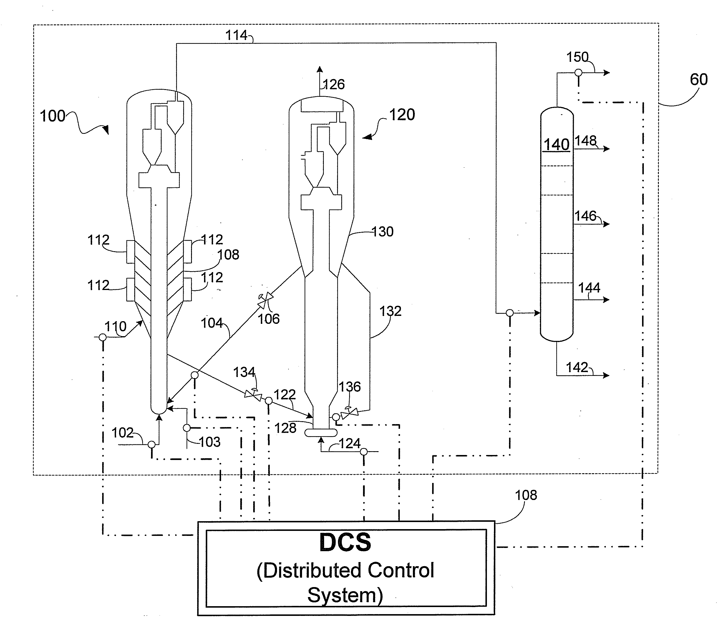
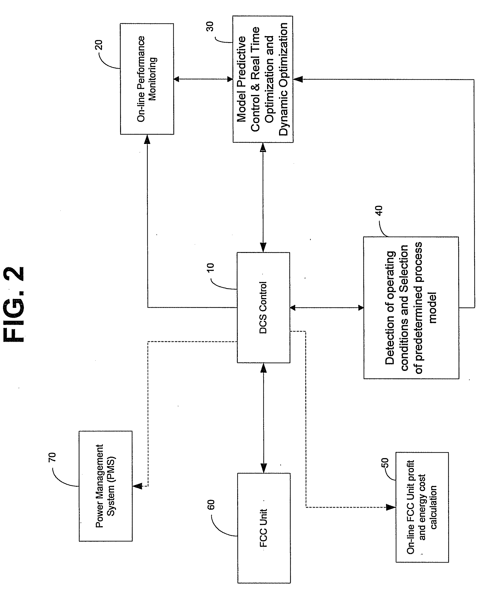
[0012]The process control system (PCS) is operable to control operating conditions of the FCC unit via control parameters. These control parameters include: obtaining predetermined process models; monitoring feed data, products characterization data, and operating conditions; selecting one of the predetermined process models based on the monitored feed data, monitored products characterization data and monitored operating conditions; selecting one of the predetermined process models based on the monitored feed data, monitored products characterization data and monitored operating conditions; calculating simulated-optimized-operating conditions using the selected predetermined process model; adjusting the operating conditions to correspond with the simulated-optimized-operating-conditions; measuring a propylene concentration in the product stream; measuring energy usage of the fluid catalytic cracking unit; comparing the propylene concentration with a predetermined propylene concentration range; comparing the energy usage of the fluid catalytic cracking unit with a predetermined energy usage range; and adjusting the operating conditions until propylene concentration falls within the predetermined minimum propylene specification to yield optimized propylene production. In one embodiment of the present invention, the optimized propylene production is defined as maximizing the ratio of propylene production over energy usage, with the energy usage being the energy consumed by the FCC unit.

Problems solved by technology

Although efforts are made to reduce side effects from the reaction, a small amount of unwanted products are produced, which include: liquefied petroleum gas (LPG), cracked gas oil and the like, and coke, which is deposited on the catalyst and thereby reduces the catalyst's effectiveness.
However, the methods taught by the above references failed to produce sufficient light-fraction olefins selectively.
For example, the methods taught by using a reduced catalyst contact time resulted in a decrease in the conversion of light-fraction olefins to light-fraction paraffins due to the methods' inhibition of a hydrogen transfer reaction.
Furthermore, the lack of hydrogen transfer also led to a decrease in the conversion of heavy-fraction oils to light-fraction oils.
The method teaching the use of the high temperature cracking reaction resulted in a concurrent thermal cracking of heavy-fraction oils, which thereby increased the yield of low-value, dry gases.
Lastly, the use of pentasil-type zeolites enhanced the yield of light-fraction hydrocarbons by excessively cracking the gasoline.
Most glaringly is the difficulty in managing the multitude of variables that must be observed and manipulated throughout the production cycle.
Since the crude oil feed varies in composition, it can be extremely challenging for operations personnel to manually test the properties of the incoming stream and adjust the necessary variables accordingly.
Furthermore, because the process taught by the prior art is complicated and contains a variety of manipulatable variables, it is virtually impossible for an operator to manually control the process, even with remote access via a computer, and achieve an optimum yield of light olefins.
Additionally, typical numerical methods and statistical, analysis do not provide an acceptable level of process control.
Consequently, the methods taught by the prior art do not teach a method for carrying out the process in an efficient manner and ensuring that the yield of light-fraction olefins has been maximized.
Furthermore, no methods teach optimizing the production of light-fraction olefins in relation to energy usage.

Method used


Image

  • Automation and Control of Energy Efficient Fluid Catalytic Cracking Processes for Maximizing Value Added Products
  • Automation and Control of Energy Efficient Fluid Catalytic Cracking Processes for Maximizing Value Added Products
  • Automation and Control of Energy Efficient Fluid Catalytic Cracking Processes for Maximizing Value Added Products

Examples


Embodiment Construction

[0019]The invention will be described below in more detail.

Neural Networks Modeling

[0020]Without loss of generality, a nonlinear system can be defined as

y(t)=f[Y(t−1),Y(t−2), . . . , Y(t−ny),

U(t−1),U(t−2), . . . U(t−nu)]+e(t)  (1)

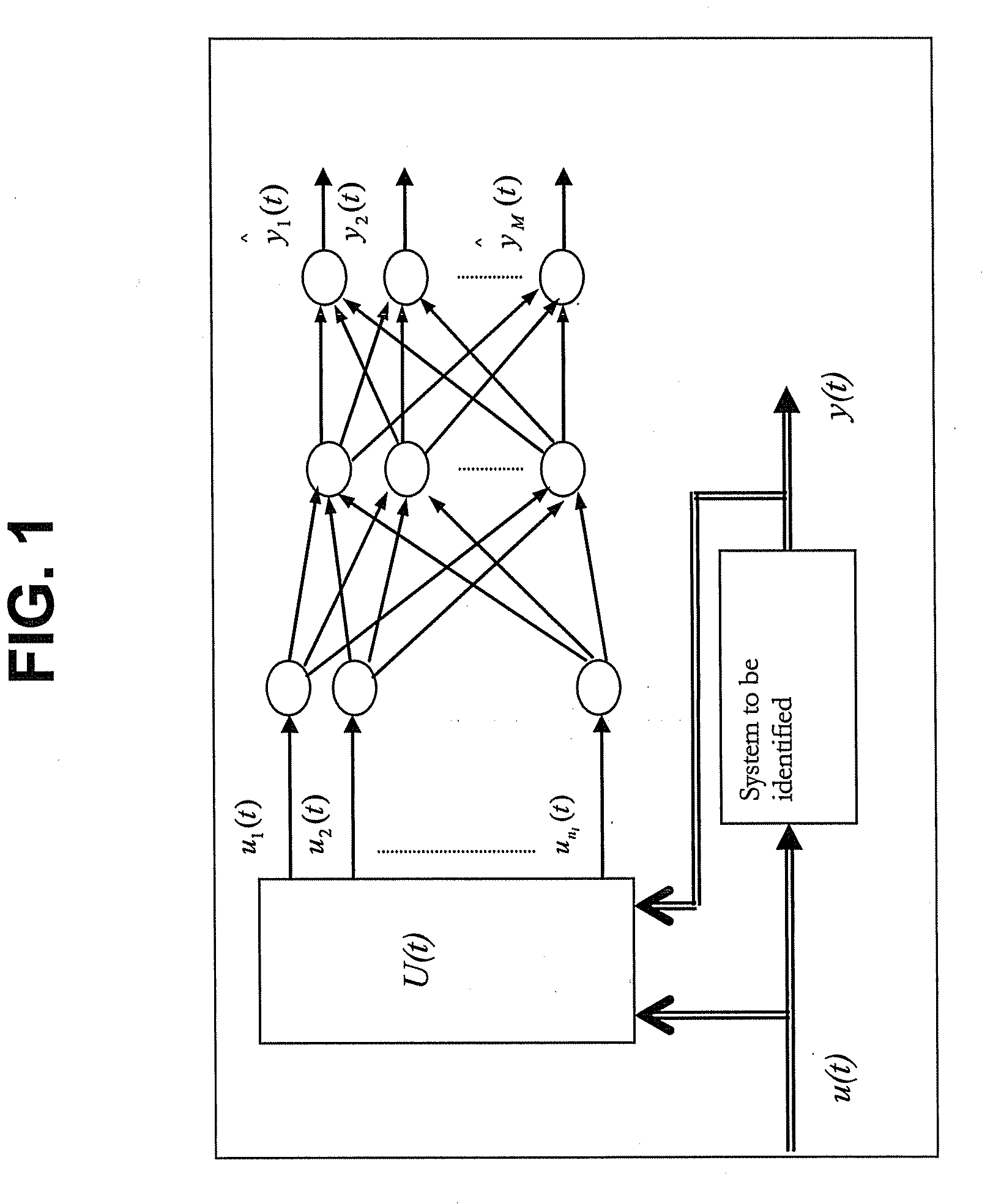
[0021]where ny and nu are the maximum lags in the output vector and the input vector e(t) is the noise. The MLP network for constructing the system mapping f(.) is shown in FIG. 1.

[0022]FIG. 1 shows three layers, but more layers are a direct generalization. The input layer has ni=nyM+nuN neurons, where M is the number of outputs and N is the number of inputs. The input vector is then defined as below:

U(t)=[u1(t),u2(t),…,uni(t)]T=[YT(t-1),YT(t-2),…,YT(t-ny),UT(t-1),UT(t-2),…UT(t-nu)]T(2)

[0023]Thus, the input vector of the network consists of the past values of the network and output vector of the system. The input layer simply feeds the vector U(t) to the hidden layer without any modification. The hidden layer has user-defined nh neurons with nonlinear trans...


PUM


Abstract

With an aim to optimize propylene production, petroleum oil is catalytically cracked by contacting the oil with catalyst mixture consisting of a base cracking catalyst containing an stable Y-type zeolite and small amounts of rare-earth metal oxide, and an additive containing a shape-selective zeolite, in an up-flow type fluid catalytic cracking apparatus having a regeneration zone, a separation zone, and a stripping zone. According to this fluid catalytic cracking process, the production of light-fraction olefins such as propylene is maximized by applying appropriate process control, monitoring, and optimizing systems. The present invention provides mathematical process models, including: neural networks, statistical models and finite impulse models. These various mathematical process models are used in conjunction with advanced controllers and optimizing routines to calculate optimal settings for various process parameters. A microwave based system can also be employed for optimizing the performance of a stripping zone, which further optimizes catalyst regeneration. Process model and historical data to test a predictive system can provide early warning of potential performance degradation and equipment failure in the FCC unit, which decreases overall operating costs and increases plant safety.

Description

RELATED APPLICATIONS[0001]This application is related to and claims priority and benefit of U.S. Non-Provisional patent application Ser. No. 11 / 983,078, filed Nov. 7, 2007, and U.S. Provisional Patent Application Ser. No. 60 / 857,300, filed Nov. 7, 2006, both of which are incorporated herein by reference in their entirety.TECHNICAL FIELD OF THE INVENTION[0002]The present invention relates to the process for catalytic cracking of petroleum oil. More particularly, the present invention relates to the application of advanced process control systems to catalytic cracking of petroleum oil in order to optimize the production of light olefins in relation to energy costs.BACKGROUND OF THE INVENTION[0003]In typical catalytic cracking techniques, the fluid catalytic cracking unit (FCC) cracks petroleum-derived hydrocarbons using a catalyst to achieve gasoline production. Although efforts are made to reduce side effects from the reaction, a small amount of unwanted products are produced, which ...

Claims


Application Information

Patent Timeline
IPC IPC(8): C10G11/00
CPCC10G11/05C10G11/187G05B13/027C10G2400/20C10G2300/1059C10G2300/107C10G2300/301G05B17/02
Inventor TAHA, OTHMAN A.KHAN, M. RASHID
Owner SAUDI ARABIAN OIL CO
Learn More