Fuel supply apparatus for and pressure control method of internal combustion engine

a technology of pressure control method and fuel supply apparatus, which is applied in the direction of combustion air/fuel air treatment, machines/engines, instruments, etc., can solve the problems of large amount of fuel vapor generated, large leakage of fuel vapor from leakage, and long time for internal pressure of the fuel tank to become, etc., to achieve high responsibility

Inactive Publication Date: 2007-04-19
HITACHI LTD
View PDF36 Cites 19 Cited by
  • Summary
  • Abstract
  • Description
  • Claims
  • Application Information

AI Technical Summary

Benefits of technology

[0010] Therefore, taking into consideration the above problems, an object of the present invention is to provide a fuel supply apparatus for an internal combustion engine and a pressure control method of an internal combustion engine by which a pressure in a fuel tank is converged on a target pressure in a steady state, with high responsibility.

Problems solved by technology

However, even if execution of pressurization or pressure reduction is stopped to open the fuel tank to the atmosphere through the canister when the leak diagnosis is completed, it may take a long time for an internal pressure of the fuel tank to become a pressure in a steady state (i.e., at around the atmospheric pressure) in some cases, depending on a tank shape or a condition of the canister.
When the leak diagnosis is carried out by pressurizing the inside of the fuel tank, if the internal pressure of the fuel tank is kept high even after the diagnosis is completed, and if there is a leak, a leakage of the fuel vapor from the leak becomes large.
When the leak diagnosis is carried out by reducing the pressure inside the fuel tank, since the fuel is likely to be vaporized when the pressure in the fuel tank is low, if the pressure-reduced state continues for a long time after the diagnosis is completed, a large quantity of fuel vapor may be generated.
Moreover, if a large quantity of fuel vapor is generated, the fuel vapor may be easily permitted to leak or flow toward the outside of a vehicle.

Method used


Image

  • Fuel supply apparatus for and pressure control method of internal combustion engine
  • Fuel supply apparatus for and pressure control method of internal combustion engine
  • Fuel supply apparatus for and pressure control method of internal combustion engine

Examples


Embodiment Construction

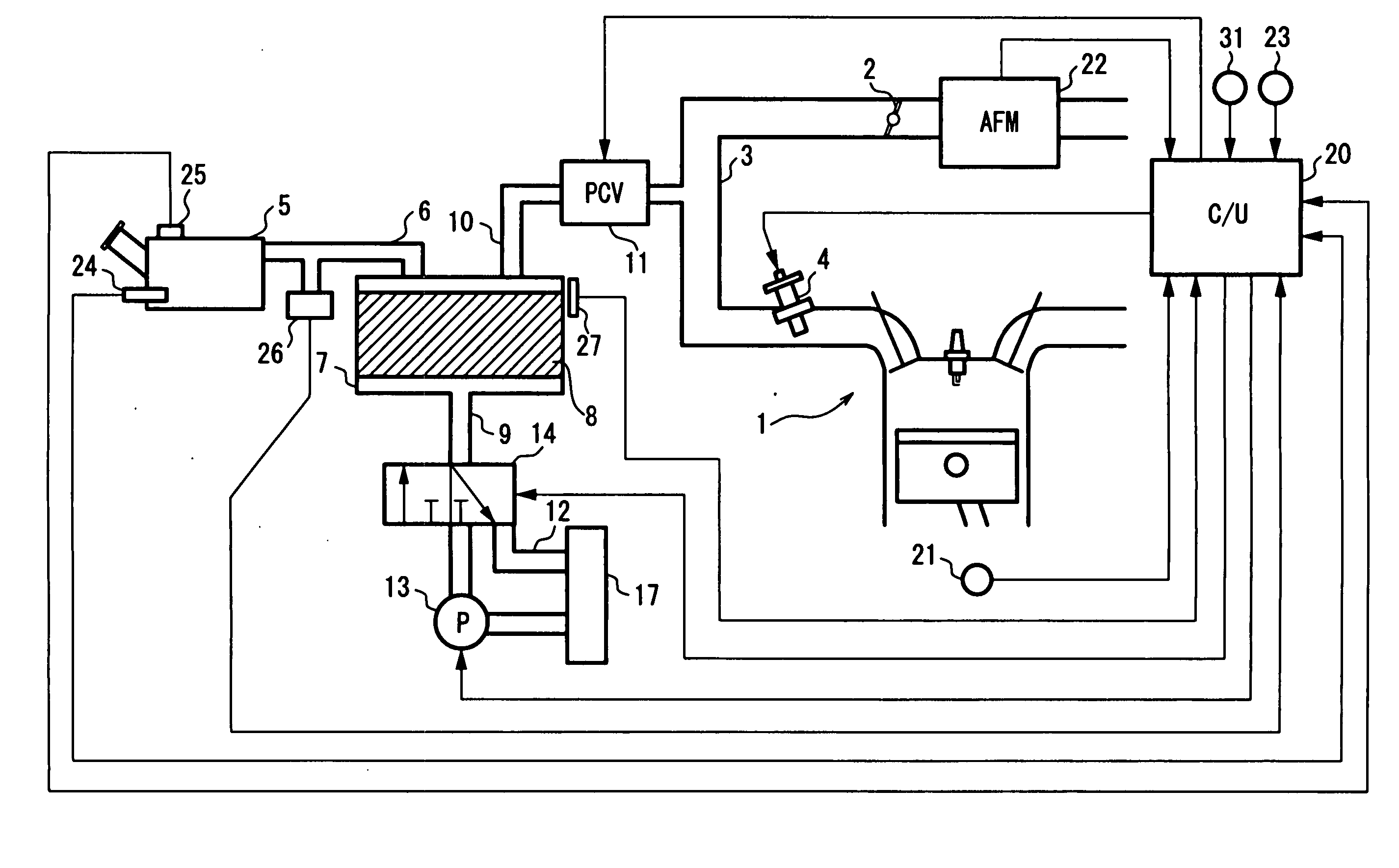
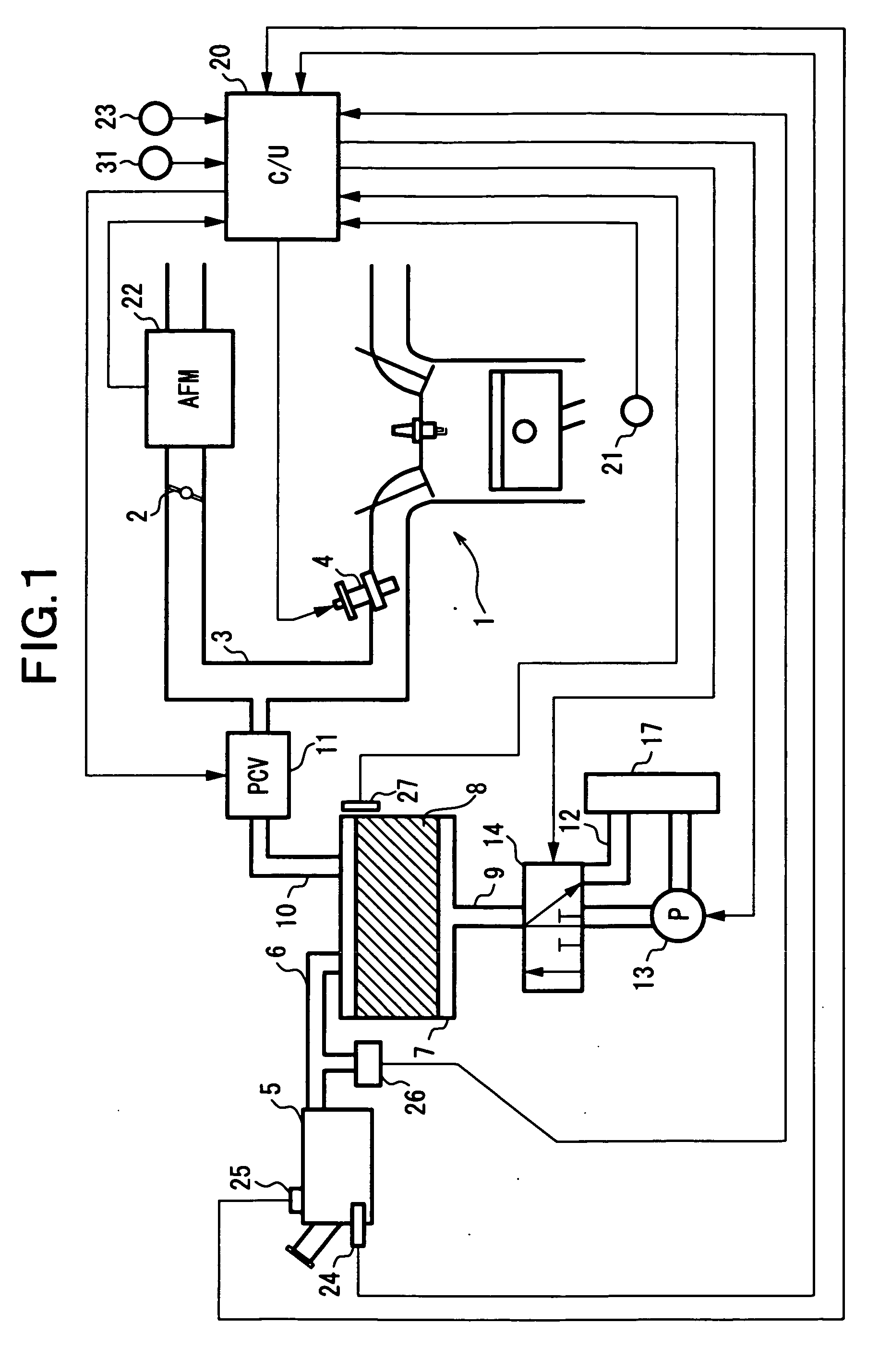
[0023]FIG. 1 is a system chart of an internal combustion engine for a vehicle.

[0024] In FIG. 1, a throttle valve 2 is provided in an intake passage 3 of an internal combustion engine 1. An intake air amount of engine 1 is regulated by an opening degree of throttle valve 2. In intake passage 3 on a downstream side of throttle valve 2, an electromagnetic fuel injection valve 4 is provided for each cylinder. Fuel injection valve 4 opens in response to a driving signal outputted from a control unit 20. Fuel stored in a fuel tank 5 is force-fed to fuel injection valve 4 by a fuel pump (not shown in the figure). A fuel vapor generated in fuel tank 5 is adsorbed and collected by a canister 7 through a fuel vapor passage 6. Canister 7 is a container in which an adsorbent 8 such as activated carbon is filled. Afresh air introducing port 9 is formed in canister 7 and a purge passage 10 is led out from canister 7.

[0025] Purge passage 10 is connected to intake passage 3 on a downstream side o...


PUM


Abstract

A leak diagnosing technology in which a diagnostic space capable of being closed is defined which includes therein a fuel tank and a canister, the closed diagnostic space being pressurized by an air pump to diagnose of presence or absence of a leak in the diagnostic space based on whether or not a pressure in the diagnostic space indicates a predetermined pressure change. When the diagnosis is completed, the air pump is reversely rotated to cause a reduction in the pressure in the diagnostic space to thereby quickly return the pressure to a target pressure in a steady state.

Description

BACKGROUND OF THE INVENTION [0001] 1. Field of the Invention [0002] The present invention relates to a fuel supply apparatus for and a pressure control method of an internal combustion engine, and particularly relates to a technique of controlling pressure in a fuel tank. [0003] 2. Description of the Related Art [0004] Japanese Unexamined Patent Publication No. 05-272417 discloses an apparatus for determining that a hole or leak has occurred when an inside of the fuel tank is pressurized by a pump and a pressure in the fuel tank cannot be increased to a predetermined pressure. [0005] Japanese Unexamined Patent Publication No. 05-180098 also discloses an apparatus for diagnosing whether a leak is present or absent based on a reduction in a fuel-tank internal pressure in response to an intake negative pressure of an internal combustion engine which negative pressure is introduced into a fuel tank to prevail thereinside. [0006] Furthermore, Japanese Unexamined Patent Publication No. 20...

Claims


Application Information

Patent Timeline
Patent Type & Authority Applications(United States)
IPC IPC(8): G01M19/00G01M99/00
CPCF02M25/0818
Inventor TAKAYANAGI, KEIICHI
Owner HITACHI LTD
Why Eureka
Try Eureka