Hole repair technique and apparatus

a hole repair and apparatus technology, applied in the direction of soldering apparatus, turbines, manufacturing tools, etc., can solve the problems of not being able to carry the load of the repaired structure, the repair is not a structural repair, and the removal of parent substrate material is excessiv

Inactive Publication Date: 2007-04-19
RAYTHEON TECH CORP
View PDF18 Cites 34 Cited by
  • Summary
  • Abstract
  • Description
  • Claims
  • Application Information

AI Technical Summary

Benefits of technology

[0003] The present invention provides an alternative method for repairing damage to a substrate with a hole. Hole defect repair according to the present invention includes removing one or more defects at or near a desired hole shape in a substrate by removing a non-concentri...

Problems solved by technology

However, known repair techniques cause excessive removal of parent substrate material.
However, this type of r...

Method used


Image

  • Hole repair technique and apparatus
  • Hole repair technique and apparatus
  • Hole repair technique and apparatus

Examples


Embodiment Construction

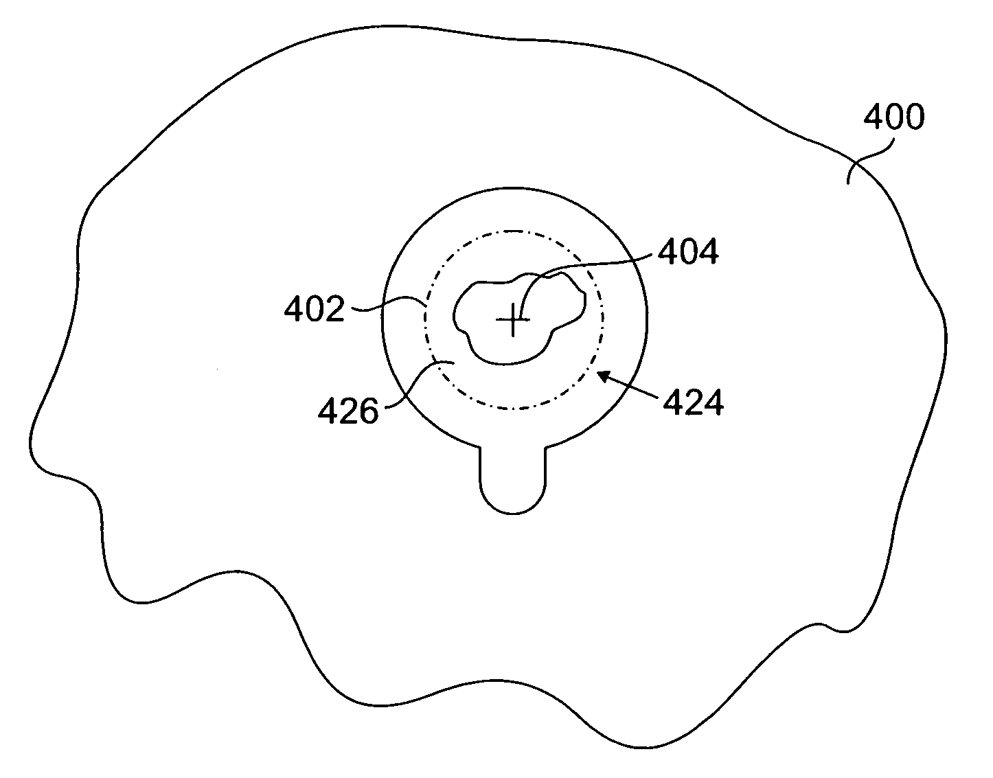
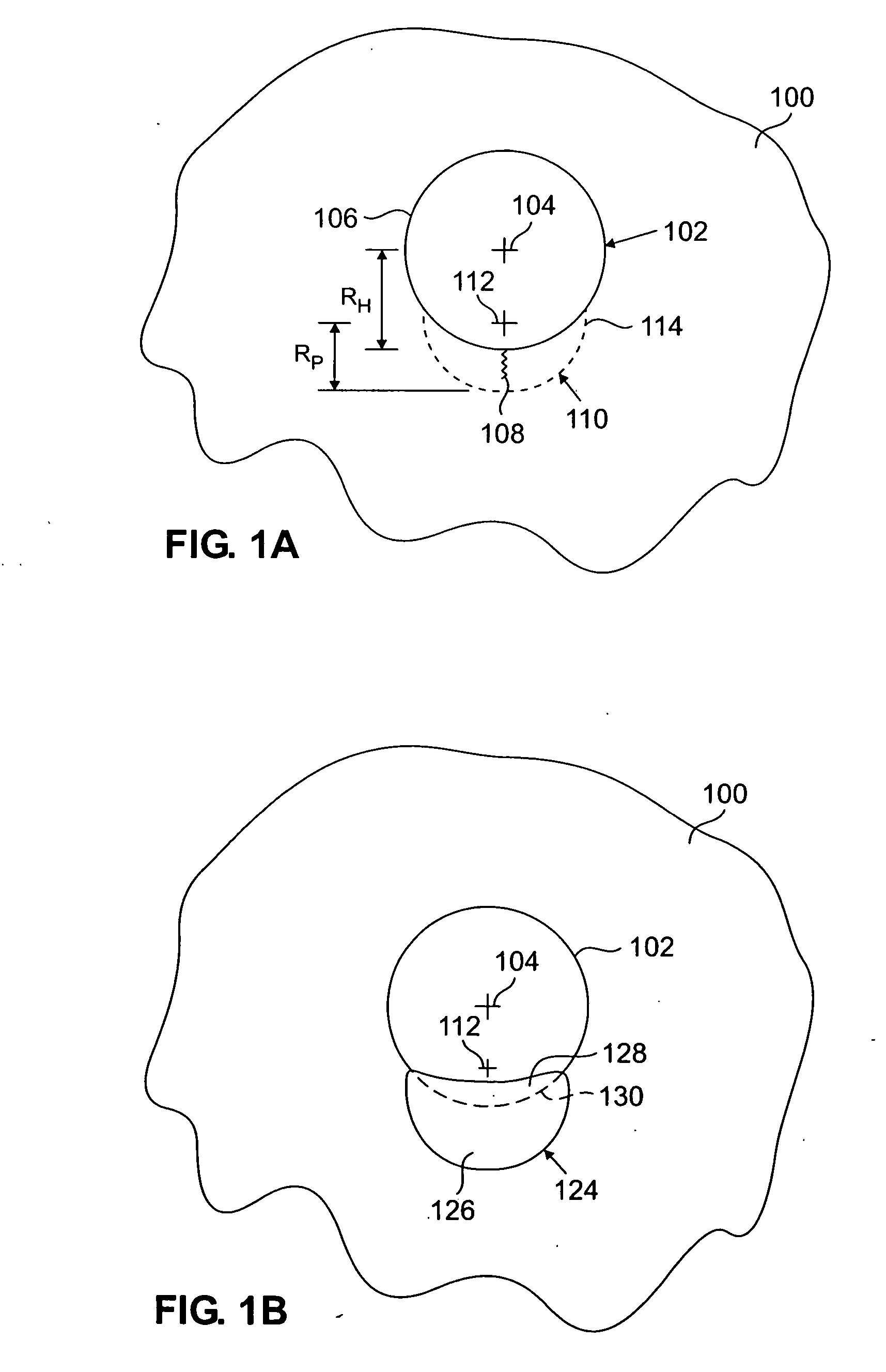
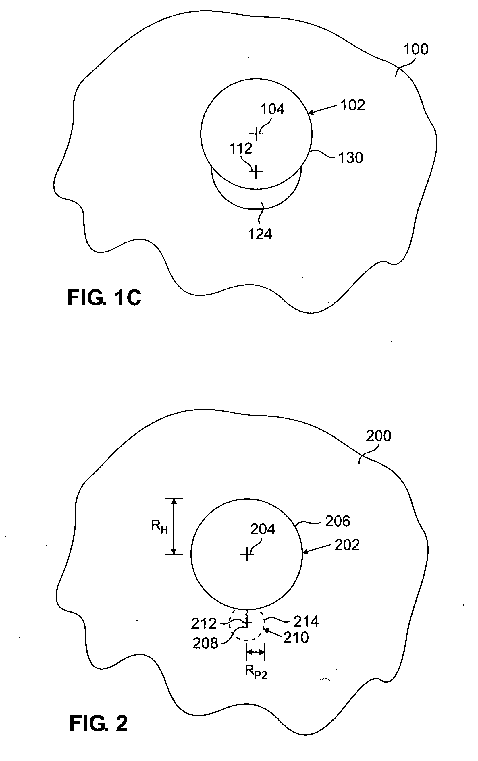
[0015] Metal parts having bolt holes, rivet holes, and other similar holes and openings can become worn, corroded, or otherwise oversized or damaged. Damage at or near such holes can include circumferential damage, cracks, corrosion, pitting, elongation, etc. due to localized wear. Such damage can be repaired to return the part, and more specifically the hole formed in the part, back to desired specifications (i.e., returning the hole to blueprint specifications). According to the present invention, the damage can be removed by first conducting localized machining (or other suitable material removal processes) and then welding the part with additional material to provide a hole with desired characteristics (e.g., size, shape and location). In some situations, additional finishing steps, such as additional machining, may be conducted to complete the repair process.

[0016] In order to repair a damaged substrate, the damage is first identified. Known nondestructive inspection (NDI) tec...


PUM

PropertyMeasurementUnit
Diameteraaaaaaaaaa
Shapeaaaaaaaaaa
Circumferenceaaaaaaaaaa

Abstract

A method of hole defect repair includes removing one or more defects at or near a desired hole shape in a substrate by removing a non-concentric portion of the substrate proximate the desired hole shape, and welding a filler material to the substrate after removing the non-concentric portion of the substrate.

Description

BACKGROUND OF THE INVENTION [0001] The present invention relates to methods of repairing substrates, and more particularly to methods of repairing damaged substrates having holes disposed therethrough. [0002] It is possible to repair worn, corroded, or otherwise damaged holes in metallic substrates. However, known repair techniques cause excessive removal of parent substrate material. For instance, in order to repair a crack that has formed at a perimeter of a rivet hole in a flange made of 6061 aluminum (Al), the hole is remachined to a larger diameter to remove the crack. In other words, a circular hole would be remachined co-axially with the centerline axis of the existing (and damaged) rivet hole and to a diameter larger than the desired (i.e., blueprint) rivet hole diameter. A bushing is then press-fit or adhesively bonded to the flange inside the remachined hole to produce a repaired hole at the desired blueprint specifications, for parameters such as size and shape. However, ...

Claims


Application Information

Patent Timeline
IPC IPC(8): B23K31/00B23K31/02
CPCB23K33/004B23K2201/001B23P6/007B23P6/045Y10T29/49728F05D2230/80F05D2230/232Y10T29/49318F01D5/005B23K2101/001
Inventor VARGAS, CHRISMULLOOLY, JOHN F.BROWN, ALLEN WAYNE
Owner RAYTHEON TECH CORP
Why Eureka
Try Eureka