Imaging device

Inactive Publication Date: 2007-04-19
SANYO ELECTRIC CO LTD
View PDF11 Cites 7 Cited by
  • Summary
  • Abstract
  • Description
  • Claims
  • Application Information

AI Technical Summary

Benefits of technology

[0026] The above second imaging device of the present invention repeats a series of photographing operations including a transfer operation in a cycle same as or longer than a period during which the series of photographing operations are performed. Therefore, a transfer operation included in the previous or next series of photographing operations is not performed within a period of the current series of photographing operations during which the transfer operation included therein is not performed, so that, during this period, the vertical transfer pulse and/or horizontal transfer pulse is stopped from being fed from the drive unit to the solid-state image sensing device. As describ

Problems solved by technology

However, the conventional digital still cameras have been suffering from a problem of increased power consumption because a series of photographing operations are performed every one vertical period as shown in FIG. 8 and FIG. 9, so that the subpulse φSUB is fed to the solid-state image sensing device

Method used


Image

  • Imaging device
  • Imaging device
  • Imaging device

Examples


first embodiment

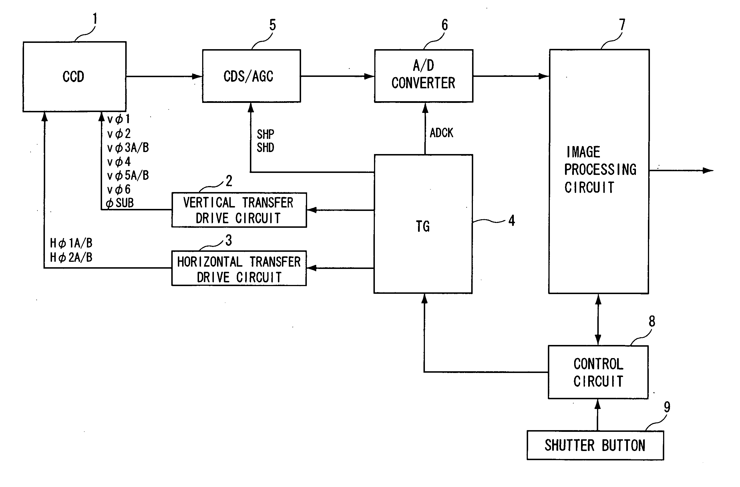
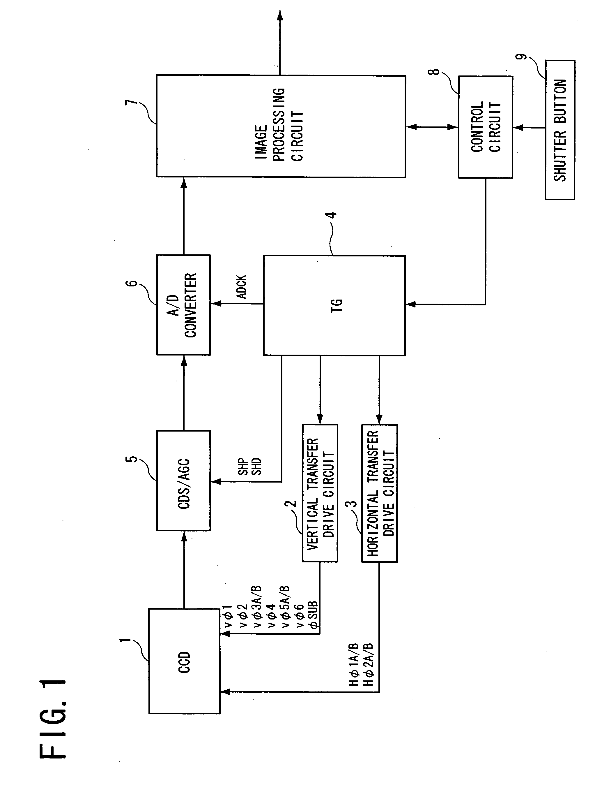
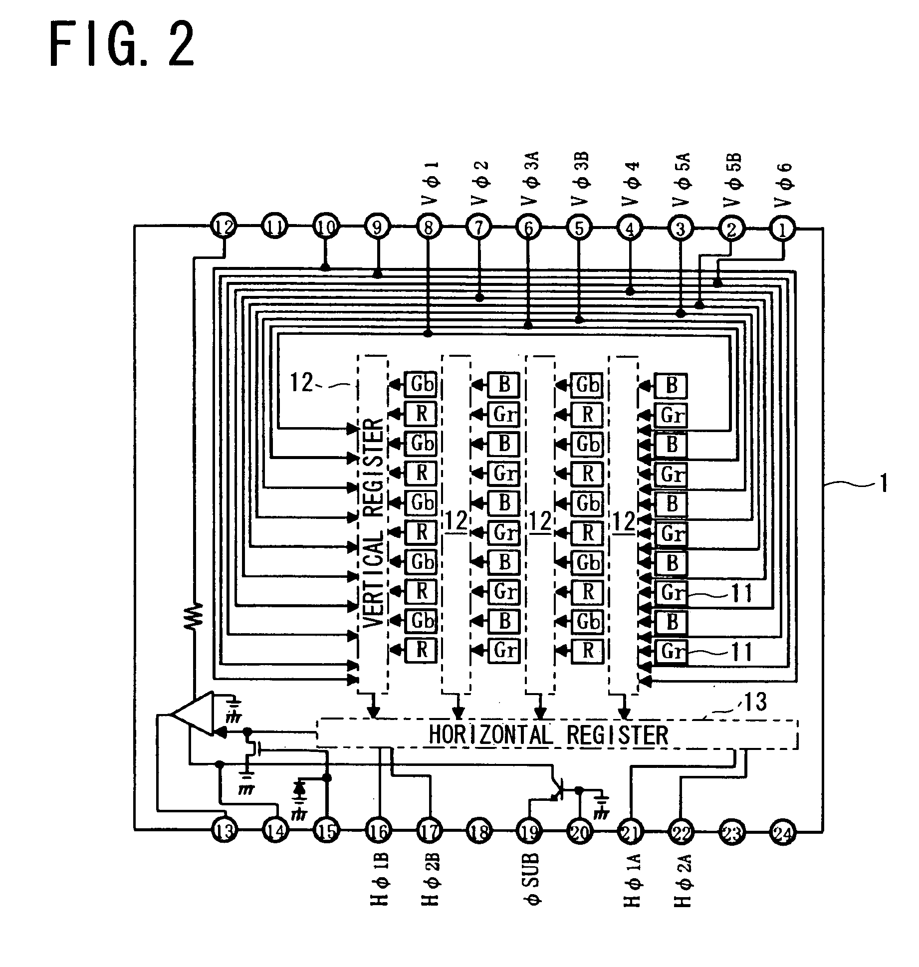
[0038] A digital still camera of the present invention includes a solid-state image sensing device 1 shown in FIG. 2. The solid-state image sensing device 1 has an input terminal 8 for a first vertical transfer pulse Vφ1 having a first phase, an input terminal 7 for a second vertical transfer pulse Vφ2 having a second phase, input terminals 6, 5 for a pair of third vertical transfer pulses Vφ3A and Vφ3B having a third phase, an input terminal 4 for a fourth vertical transfer pulse Vφ4 having a fourth phase, input terminals 3, 2 for a pair of fifth vertical transfer pulses Vφ5A and Vφ5B having a fifth phase, and an input terminal 1 for a sixth vertical transfer pulse Vφ6 having a sixth phase.

[0039] The solid-state image sensing device 1 also has input terminals 21, 16 for a pair of first horizontal transfer pulses Hφ1A and Hφ1B, and input terminals 22, 17 for a pair of second horizontal transfer pulses Hφ2A and Hφ2B provided by inverting the first horizontal transfer pulses. The sol...

second embodiment

[0059] Whereas the digital still camera of the first embodiment has a calculation time for an exposure time and a focus adjustment value exceeding one vertical period as shown in FIG. 3, a digital still camera of the present embodiment has a calculation time less than one vertical period.

[0060]FIG. 5 shows operations of the digital still camera of the present embodiment at a time when a shutter button is depressed, and the vertical transfer pulses Vφ1-Vφ6, horizontal transfer pulses Hφ1A, Hφ1B, Hφ2A, Hφ2B, and subpulse φSUB to be fed to the solid-state image sensing device 1. SHT in FIG. 5 is a shutter pulse generated upon depression of the shutter button, and VD is a vertical synchronizing pulse. The vertical transfer pulses, horizontal transfer pulses and subpulse are a rectangular pulse. One block of the horizontal transfer pulses in FIG. 5 represents a series of horizontal transfer pulses.

[0061] When the shutter button is depressed, in a first vertical period (#1V), a series o...

third embodiment

[0064] As shown in FIG. 6, a digital still camera of a third embodiment employs an operation for reducing an output number of the subpulse φSUB, instead of an operation for stopping feeding the subpulse φSUB in the above first embodiment. Step S5′ shown in FIG. 7 gives a sub-timing pulse output number reduction command. This would also reduce the power consumption to less than that of conventional digital still cameras.

[0065] The present invention is not limited to the foregoing embodiments in construction but can be modified variously by one skilled in the art without departing from the spirit of the invention as set forth in the appended claims. For example, the present invention may be embodied in a digital still camera including a three-phase drive system solid-state image sensing device or four-phase drive system solid-state image sensing device, although the above embodiments are digital still cameras including a six-phase drive system solid-state image sensing device 1 shown...


PUM


Abstract

An imaging device of the present invention includes a solid-state image sensing device; a vertical transfer drive circuit for feeding a subpulse to the solid-state image sensing device; and a control circuit, and repeats a series of photographing operations in a cycle same as or longer than a period during which the series of photographing operations are performed, the series of photographing operations including an exposure operation for exposing an imaging area after the subpulse is fed to the solid-state image sensing device to sweep out electric charges accumulated in pixels. The control circuit stops the subpulse from being fed from the vertical transfer drive circuit to the solid-state image sensing device during a period during which the exposure operation included in the series of photographing operations is not performed.

Description

FIELD OF THE INVENTION [0001] The present invention relates to an imaging device such as a digital still camera including a solid-state image sensing device including a CCD or the like. BACKGROUND OF THE INVENTION [0002] Digital still cameras including a solid-state image sensing device including a CCD or the like have become popular in recent years. FIG. 2 shows a configuration of an interline transfer solid-state image sensing device 1 used for a digital still camera. The solid-state image sensing device 1 forms an imaging area including a plurality of pixels 11 by having color filter arrays on a plurality of photo sensors arranged in the form of a matrix, and has a plurality of vertical registers 12 for transferring electric charges of a plurality of arrays of vertically arranged pixels 11, and a horizontal register 13 for outputting the electric charges transferred by these vertical registers 12 every one horizontal period. [0003] The above solid-state image sensing device 1 has...

Claims


Application Information

Patent Timeline
IPC IPC(8): H04N5/335H04N5/353H04N5/3728H04N5/376
CPCH04N3/1537H04N5/232H04N5/23241H04N5/3728H04N25/625H04N25/72H04N25/73H04N25/75
Inventor KIDO, KENICHI
Owner SANYO ELECTRIC CO LTD
Why Eureka
Try Eureka