
Liquid particle mass measurement in gas streams

a gas stream and liquid particle technology, applied in the field of liquid particle/droplet detection system, can solve the problems of reducing the efficiency of hydrogenation catalyst, causing pressure drop across hydrogenator/desulfurizer, and undesirable occurren

Inactive Publication Date: 2007-04-19
AIR PROD & CHEM INC
View PDF5 Cites 15 Cited by
  • Summary
  • Abstract
  • Description
  • Claims
  • Application Information

AI Technical Summary

Benefits of technology

The patent describes a detection system for detecting the presence of fine liquid particles in a gas system, such as an aircraft ventilation system or a natural gas system. The system includes a monitor, a data acquisition unit, and pressure and flow control means. The monitor detects the presence of fine liquid particles using light scattering and sends a signal to the data acquisition unit. The pressure and flow control means ensures that the pressure and flow rate of the gas at the monitor are within a predetermined range. The data acquisition unit provides an output signal that indicates an absolute value change in the mass count of any fine liquid particles in the gas system. The system can automatically adjust the pressure and flow control means based on the data from the data acquisition unit. The technical effect of this invention is to provide a reliable and automated way to detect the presence of fine liquid particles in gas systems, which can help to improve operational efficiency and prevent damage or malfunctions.

Problems solved by technology

Moreover, oil mist in natural gas feed stock may reduce the efficiency of the hydrogenation catalyst by deactivating it and also causing it to “cake”, thereby creating a pressure drop across a hydrogenator / desulfurizer.
Obviously, this occurrence is undesirable.
For some gas carrying systems, e.g., natural gas reformation system, HVAC systems such as in aircraft, clean rooms or other controlled environments in manufacturing facilities etc., the prior art systems as disclosed above may not be suitable, e.g., they may be too complex or expensive.

Method used


Image

  • Liquid particle mass measurement in gas streams
  • Liquid particle mass measurement in gas streams
  • Liquid particle mass measurement in gas streams

Examples


Embodiment Construction

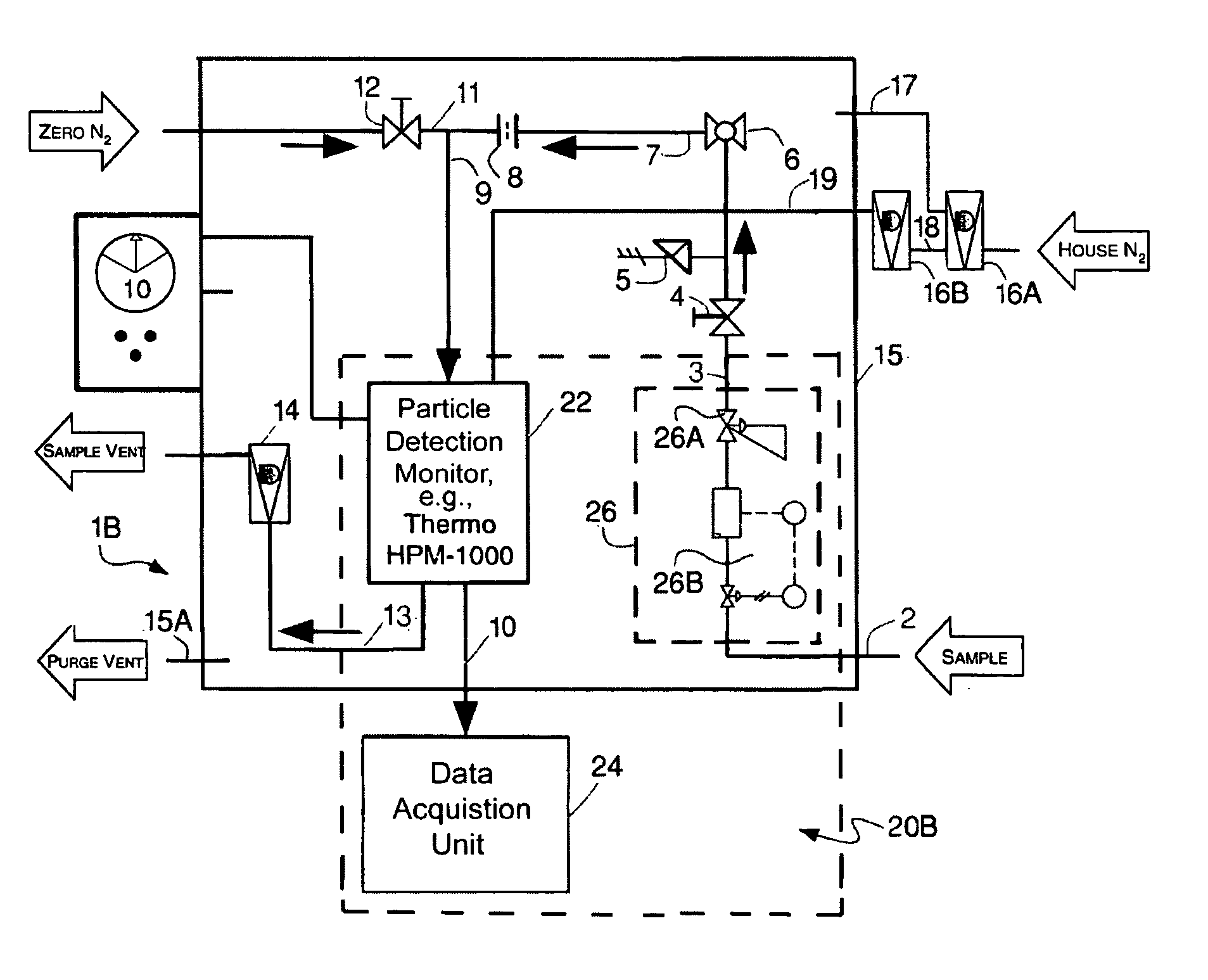
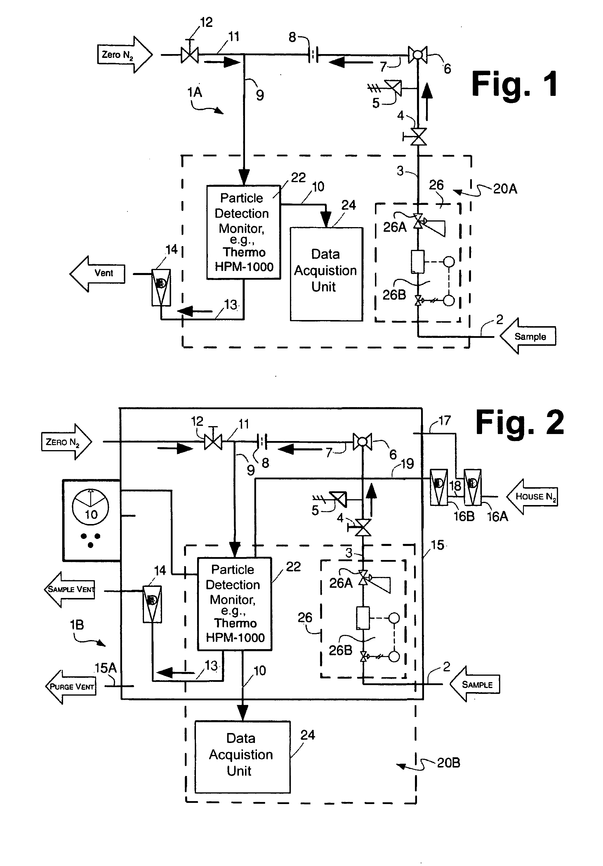
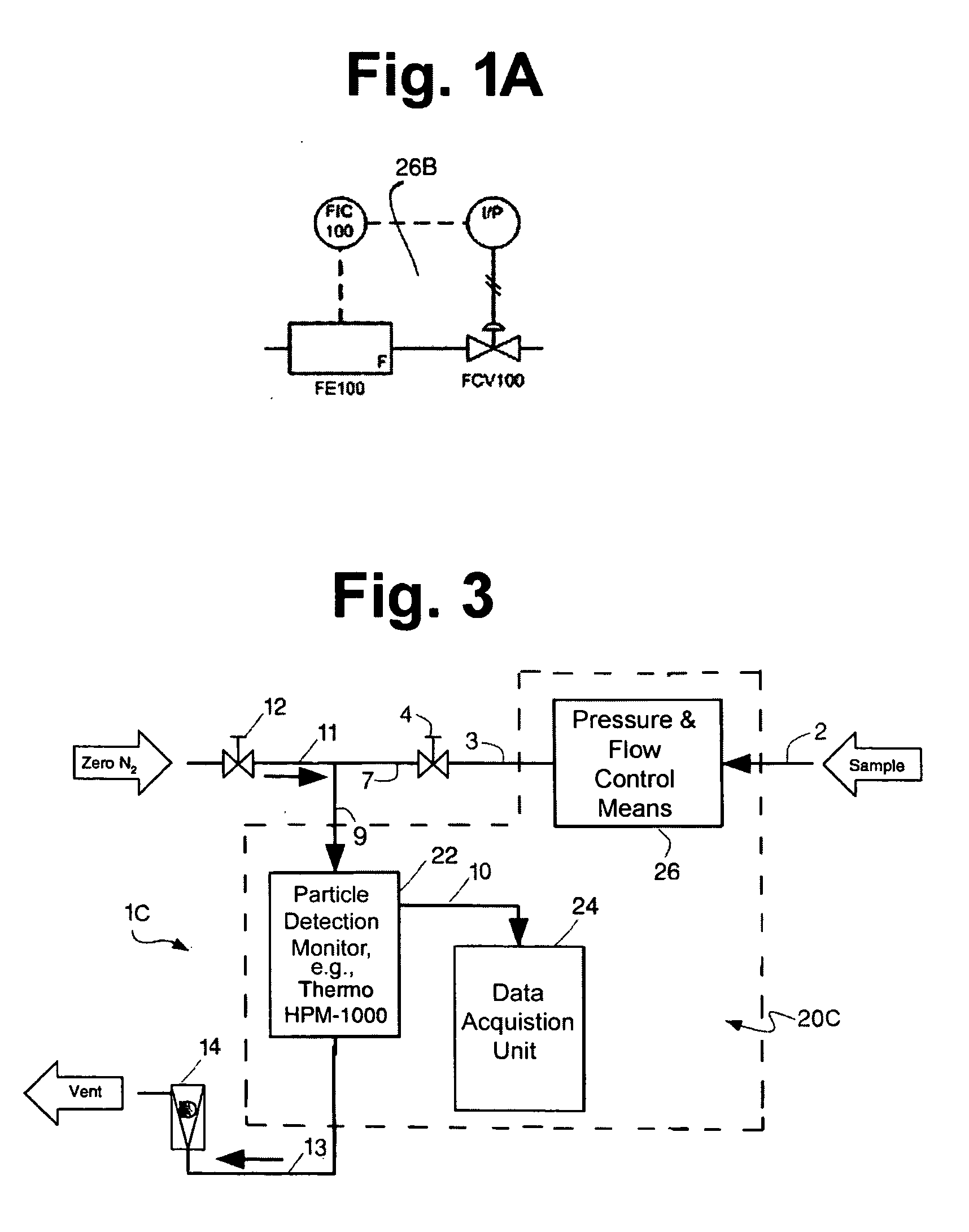
[0018] Referring now to the various figures of the drawing wherein like reference numbers refer to like parts, there is shown in FIGS. 1, 2 and 3 exemplary embodiments of fine liquid particle / droplet detection system 20A, 20B and 20C, respectively, which are constructed in accordance with this invention for use with various types of systems for through which a gas will pass. As will be described in considerable detail later each of the systems 20A, 20B and 20C comprises a single particulate detection monitor 22, an associated data acquisition unit 24 and pressure and flow control means 26. The details and operation of those components will be described later and are consistent with that described in our aforementioned co-pending patent application.

[0019] Before describing the fine liquid particle / droplet detection systems of this invention it should be pointed out that such system are useful in any gas system, like the systems of FIGS. 1-3 or any other systems wherein oil or other ...


PUM

PropertyMeasurementUnit
pressuresaaaaaaaaaa
pressuresaaaaaaaaaa
pressuresaaaaaaaaaa

Abstract

A system for detecting fine liquid, e.g., oil, particles in a gas system having a conduit through which a gas, e.g., hydrogen, air, etc., will flow. The detection system includes a monitor including a high sensitivity photometric sensor, a data acquisition unit and flow and pressure control components to control the pressure and rate of flow of the gas to the monitor. The detection system is arranged to detect the presence of fine liquid particles the gas passing through the conduit and to provide an alert signal representative of the mass count of such particles in response thereto.

Description

CROSS-REFERENCE TO RELATED APPLICATIONS [0001] This application is a Continuation-In-Part of U.S. patent application Ser. No. 11 / 249,206, filed on Oct. 13, 2005, entitled System And Methods For Detecting Liquid Particles In A Gas Stream, whose disclosure is incorporated by reference herein.BACKGROUND OF THE INVENTION [0002] This invention relates generally to liquid particle / droplet detecting systems, and more particularly to systems for detecting particles or droplets of liquids, e.g., oils, in gas systems making use of at least one gas compressor or other device which may introduce fine particles of such liquid(s) into gas in the system. [0003] As should be appreciated by those skilled in the art, in gas producing, transport and / or storage systems, such as natural gas feed stock systems, fine oil mist may enter into the conduit carrying the natural gas as a result of leakage of oil from seals of compressors. The presence of such minute particles or droplets of oil (sometimes refer...

Claims


Application Information

Patent Timeline
Patent Type & Authority Applications(United States)
IPC IPC(8): G01N21/00
CPCG01N15/06G01N2015/0693G01N15/075
Inventor SCHWEIGHARDT, FRANK KENNETHYING, DAVID HON SINGCHIN-FATT, DEAN ANTHONYFOGASH, KEVIN BOYLEKAYHART, CHARLES RANDALL
Owner AIR PROD & CHEM INC
Learn More