Network management method and communications network system

a network management and communication network technology, applied in the field of network management methods, can solve the problems of control lines in proportion to the number of nodes, increasing the number of control information is a burden on the network management system, and increasing the total traffic on the conventional communication network system, so as to avoid the increase of traffic

Inactive Publication Date: 2007-04-19
OKI ELECTRIC IND CO LTD
View PDF14 Cites 87 Cited by
  • Summary
  • Abstract
  • Description
  • Claims
  • Application Information

AI Technical Summary

Benefits of technology

[0006] It is therefore an object of the present invention to provide an improved network management method to avoid the increase in the traffic due to transferring a protocol itself.
[0007] It is another object of the present invention to provide an improved communication network system to manage the traffic congestion due to a large number of replicas excessively generated by executing the particular program.

Problems solved by technology

For that reason, it is unavoidable to increase the number of control lines and control information in proportion to the number of nodes.
Accordingly, the increase in the control information is a burden to the network management system, and the total traffic on the conventional communication network system also increases.
Furthermore, it is feared that the conventional communication network system can not accept new communication technology or cope with new communication service.
If the program commands that the node makes a plurality of replicas of the user packet and transfers the replicas to a plurality of nodes respectively, the network management system can not manage traffic congestion on the conventional communication network system.
As a result, the whole communication on the communication network system would become unusable.

Method used


Image

  • Network management method and communications network system
  • Network management method and communications network system
  • Network management method and communications network system

Examples


first embodiment

[0027] A. First embodiment of the invention

[0028] The first embodiment of the present invention will be described below with reference to a preferred embodiment in conjunction with the accompanying drawings.

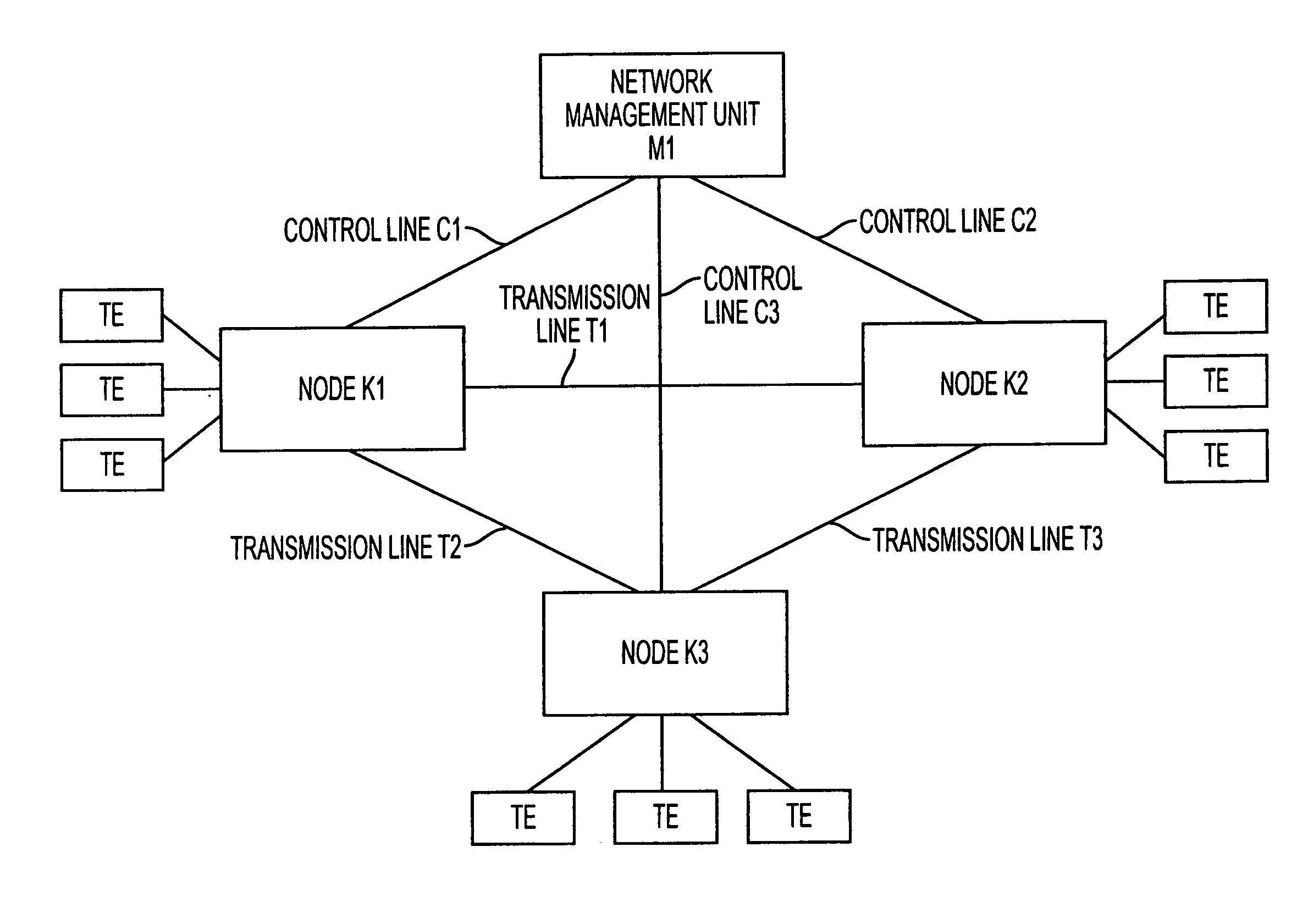
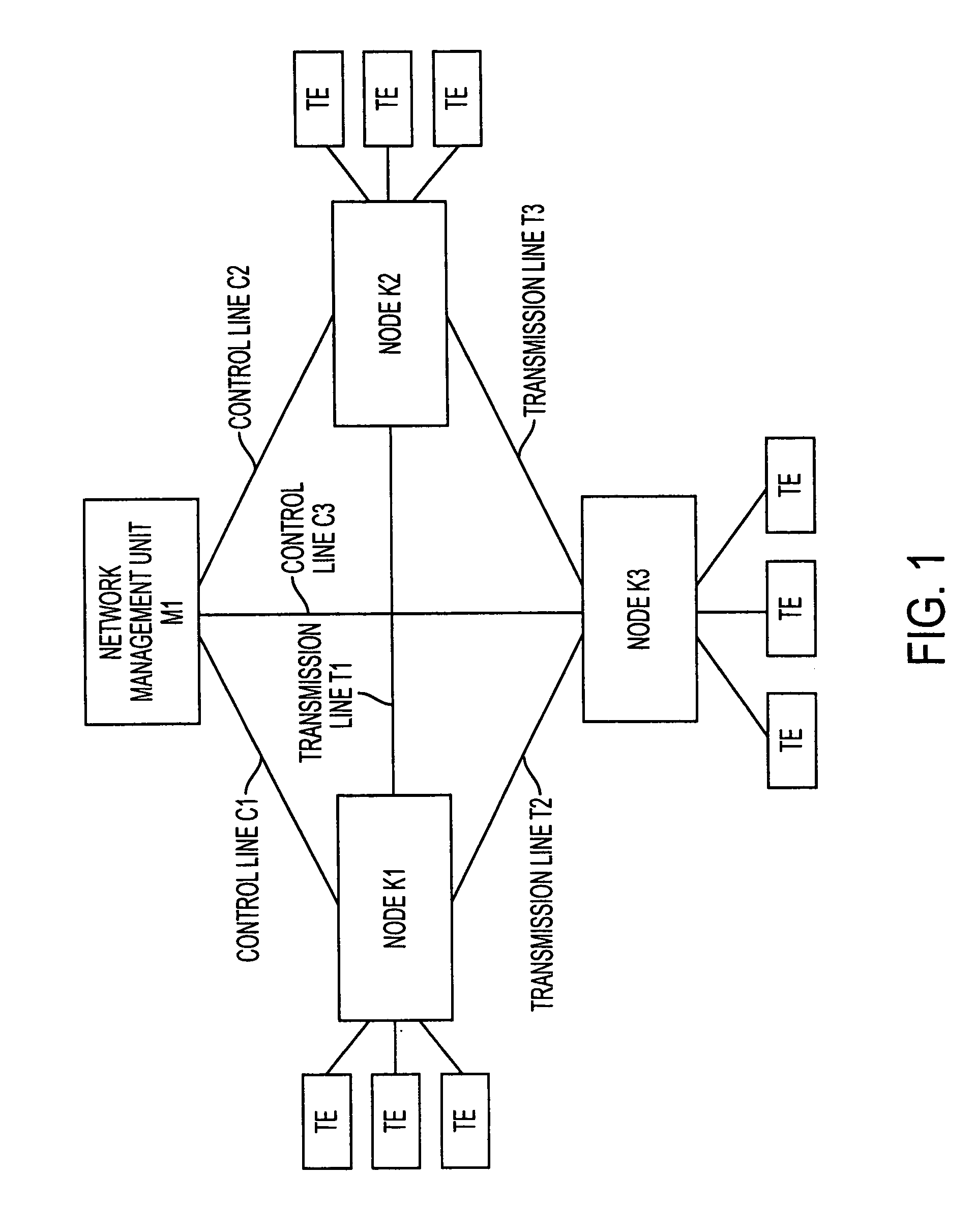
[0029]FIG. 1 shows a communications network system comprising nodes K1-K3 and a network management system M1. Each of the nodes K1-k3 is equipped with a switching function, for example a switching system or a router, and accommodates terminal equipment (TE). Accordingly, when a packet is input to a node, the node transfers it to the addressed terminal equipment (TE) by performing optimum algorithm as a transferring function. In FIG. 1, the node K1 is connected to the nodes K2 and K3 via transmission lines T1 and T2 respectively, and the node K2 is connected to the node K3 via a transmission line T3. The management system M1 is connected to the nodes K1-K3 via control lines C1-C3 respectively.

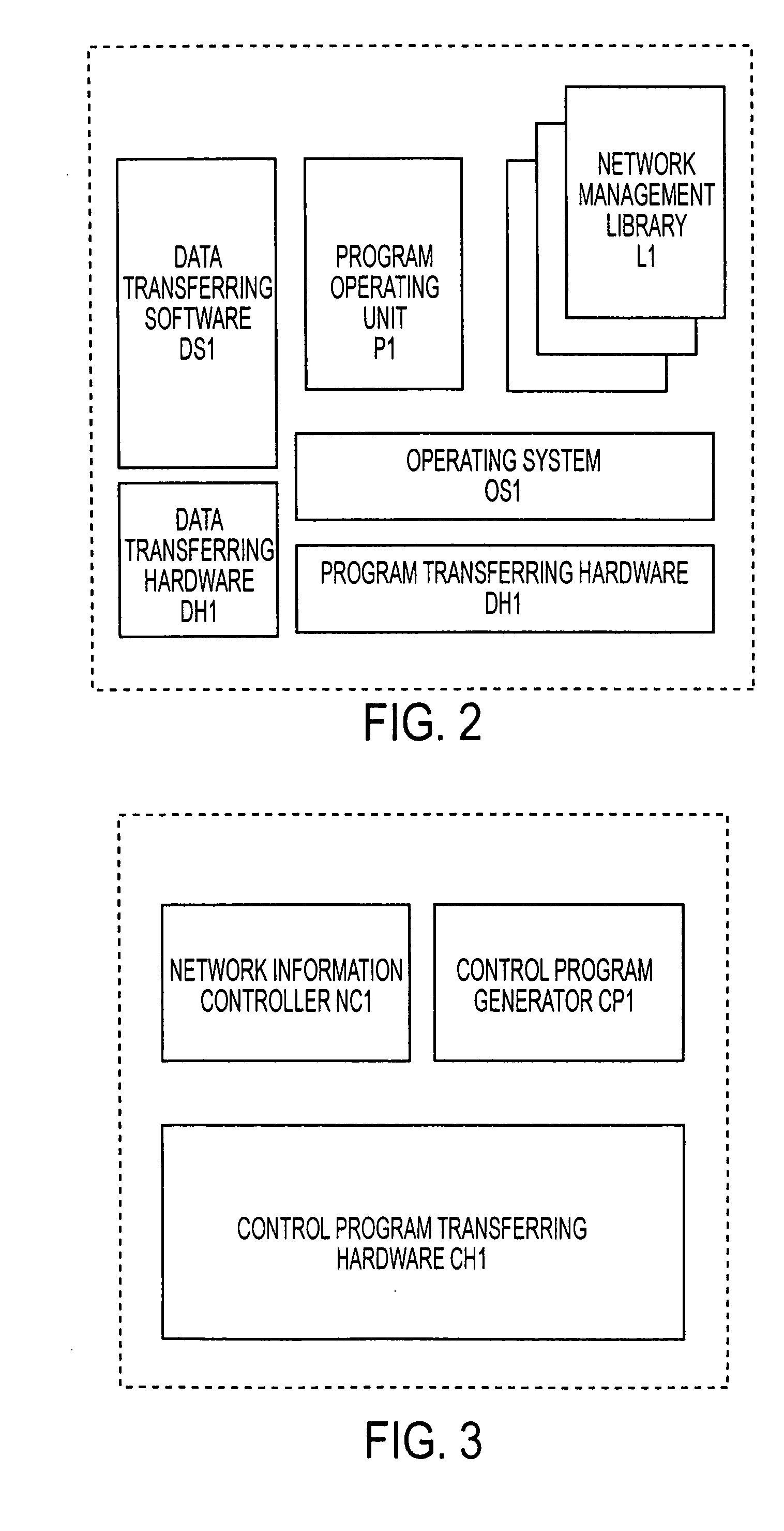
[0030]FIG. 2 shows a simplified block diagram of the nodes K1-K3. As shown in FIG. 2, e...

second embodiment

[0040] B. Second Embodiment of the Invention

[0041] The second embodiment of the invention will be described below. Since a communication network system according to the second embodiment is the same as that of the first embodiment as shown in FIG. 1, accordingly the explanation will be omitted here.

[0042]FIG. 4 shows a block diagram of nodes K1-K3 according to the second embodiment of the present invention. As shown, each of the nodes K1-K3 comprises a packet-observing element PS2, a packet-processing element PP2, an operating unit E2 and a packet transferring hardware DH2. In general, the packet-observing element PS2, the packet-processing element PP2 and the operating unit E2 are realized by software, and the packet transferring hardware DH2 comprises a central processing element (CPU), a memory and I / O interface. The packer-observing element PS2 identifies and records header information of a received packet. In addition, if packets having the same header information are received...


PUM


Abstract

This invention provides an improved data transferring method performed in a communication network comprising a management system M1 and a plurality of nodes K1-K3. Since the management system M1 collectively manages the algorithm information that indicates algorithm possessed in each node, if the fist node does not have algorithm needed for processing a certain packet, the first node can find the second node having the algorithm by inquiring the network management element M1. In addition, the first node can transfer the certain packet to the second node to process the certain packet by using the algorithm.

Description

BACKGROUND OF THE INVENTION [0001] 1. Field of the Invention [0002] The present invention generally relates to a network management method applied to a communications network system, such as a public telephone network and a data communication network. [0003] 2. Description of the Related Art [0004] In general, a conventional communication network system comprises a plurality of nodes each having a switching function and terminal equipments (TEs). The system further comprises a network management system to monitor traffic status of network communications and to manage establishment of roundabout routes. The network management system is then connected to each node via a control line, and the management of the network communication is performed via the control lines. For that reason, it is unavoidable to increase the number of control lines and control information in proportion to the number of nodes. Accordingly, the increase in the control information is a burden to the network manag...

Claims


Application Information

Patent Timeline
Patent Type & Authority Applications(United States)
IPC IPC(8): H04L12/28H04L69/40G06F13/00
CPCH04L12/24H04L41/00
Inventor KATO, KEIWANG, CAI DONG
Owner OKI ELECTRIC IND CO LTD
Why Eureka
Try Eureka