Lens-shutter coupling unit

a technology of lens-shutter and coupling unit, which is applied in the direction of shutters, mountings, instruments, etc., can solve the problems of difficult miniaturization of shutter units, insufficient size reduction of shutter units, and complicated assembly, so as to reduce the fluctuation of optical axis deviation and the deviation of optical axis.

Inactive Publication Date: 2007-04-19
SHARP KK
View PDF5 Cites 41 Cited by
  • Summary
  • Abstract
  • Description
  • Claims
  • Application Information

AI Technical Summary

Benefits of technology

[0047] According to the invention, since the lens holder is formed integrally with the bearing part into which a guide shaft that guides movement of the lens holder in the direction of the optical axis is to be inserted, the position precision of the bearing part and the optical axis of the lens group is managed, so that deviation of the optical axis c

Problems solved by technology

Accordingly, the driving unit has to be disposed further outside than the outer diameter of the lens by the thickness of the lens holder, and consequently the shutter unit cannot be reduced in size sufficiently.
Further, since the driving unit is disposed in a position apart from the optical axis, and the center of rotation of the shutter blades is apart from the optical axis, it is necessary to

Method used


Image

  • Lens-shutter coupling unit
  • Lens-shutter coupling unit
  • Lens-shutter coupling unit

Examples


Embodiment Construction

[0056] Now referring to the drawings, preferred embodiments of the invention are described below.

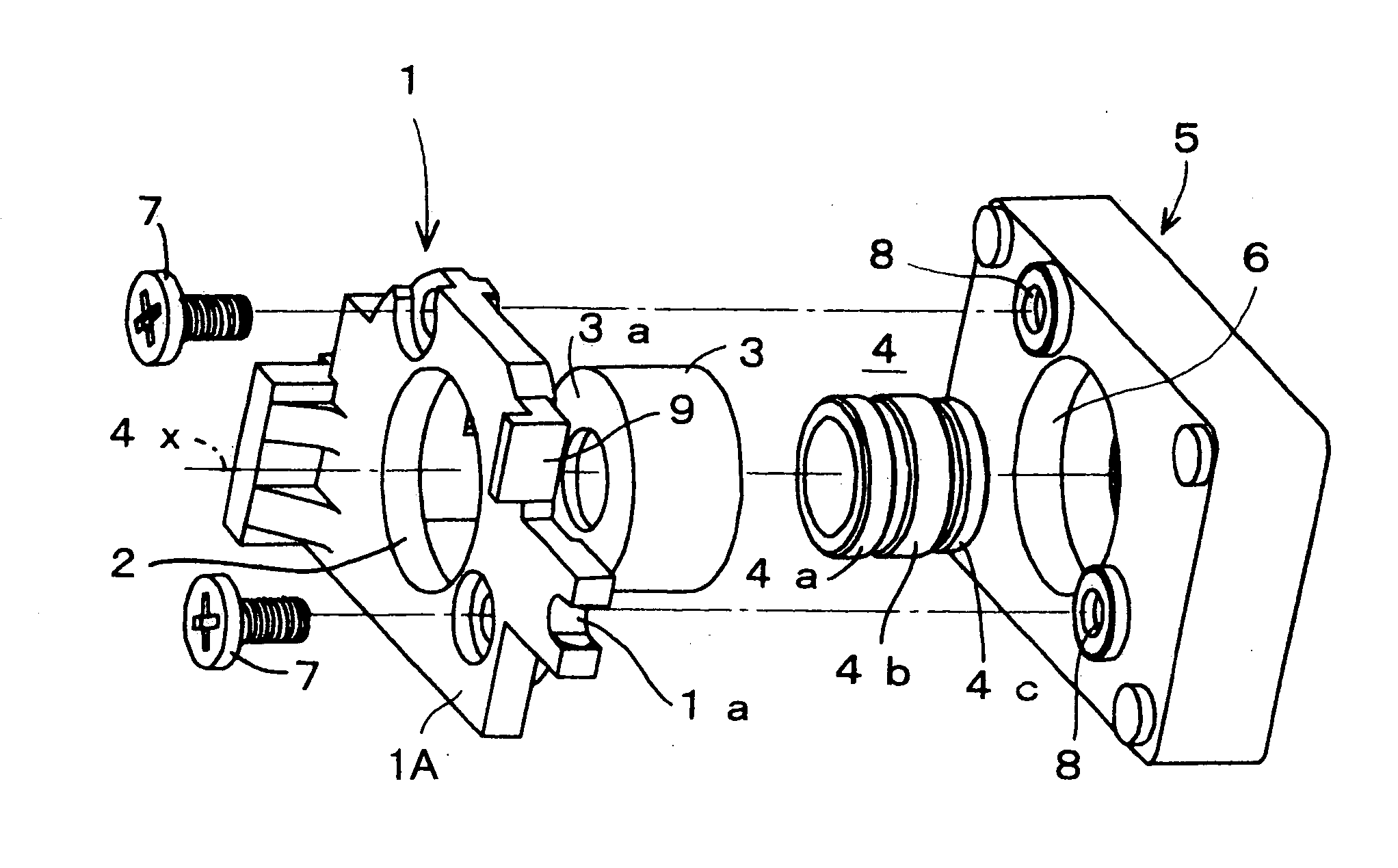
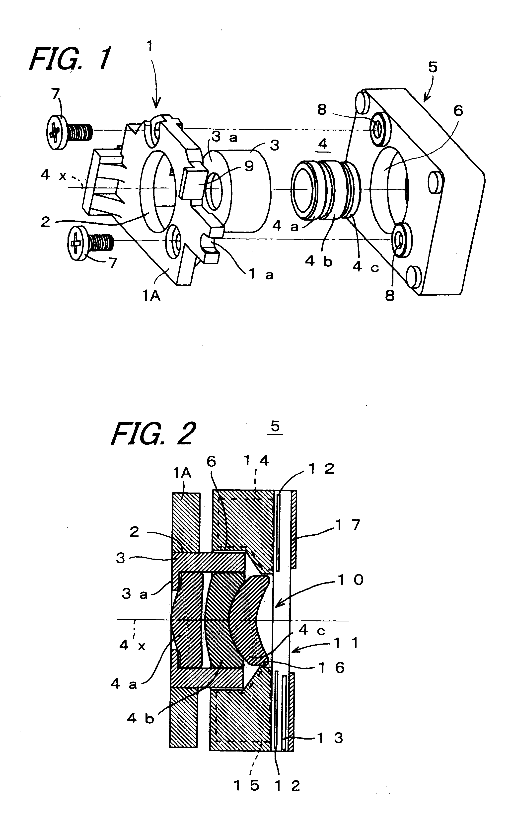
[0057]FIGS. 1 and 2 show a schematic configuration of a lens-shutter coupling unit according to an embodiment of the invention. FIG. 1 is an exploded perspective view showing a coupling structure of a lens holder and a shutter unit, and FIG. 2 shows a sectional configuration of the lens holder and the shutter unit whey they are coupled with each other.

[0058] As shown in FIG. 1, a lens holder 1 comprises a lens holder main body 1A including a holder opening 2 and a barrel 3 that is a lens fixing frame. The barrel 3 is fixedly bonded to the holder opening 2. A lens group 4 is fixed to the barrel 3 by press-fitting or bonding. The lens group 4 is constituted of, for example, three lenses 4a, 4b, and 4c. Two lenses 4b and 4c of the three lenses on the side of a shutter unit 5 are combined lenses that are fixedly bonded to each other in advance. The shutter unit 5 is provided with an openin...


PUM


Abstract

A lens-shutter coupling unit having a coupling structure of a lens shutter and a shutter unit capable of miniaturization and high-precision arrangement of a lens group, is provided. A shutter driving part for moving shutter blades and a filter driving part for moving an ND filter are disposed near an outer periphery of a protruding part of a lens group that protrudes from a barrel. The shutter driving part and the filter driving part can be disposed in a position (inner periphery) near an optical axis of the lens group. The center of rotation of the shutter blades and the ND filter can also be disposed near the optical axis of the lens group, and the shutter blades and the ND filter can be reduced in size. As a result, since the space at the time of retreat can be reduced, the shutter unit can be reduced in size.

Description

CROSS-REFERENCE TO RELATED APPLICATION [0001] This application claims priority to Japanese Patent Application No. JP 2005-299270, which was filed on Oct. 13, 2005, the contents of which, are incorporated herein by reference, in their entirety. BACKGROUND OF THE INVENTION [0002] 1. Field of the Invention [0003] The present invention relates to a lens-shutter coupling unit to be used for an optical instrument, such as an camera, and having a coupling structure of a mechanical shutter and a lens shutter. [0004] 2. Description of the Related Art [0005] In the related art, a camera or the like including an image pickup optical system composed of a plurality of lenses has been used widely. An object image that is formed on the basis of a light beam entering the image pickup optical system is focused on an image pickup device, such as an image sensor using a charge-coupled device (CCD), i.e., a CCD image sensor, which is disposed in a predetermined position. In such a camera, in order to f...

Claims


Application Information

Patent Timeline
IPC IPC(8): G03B9/08
CPCG02B5/205G02B7/026G03B9/12
Inventor FUJITA, HIDEAKI
Owner SHARP KK
Why Eureka
Try Eureka