Light diffusion sheet and backlight unit using the same

a technology of backlight unit and light diffusion sheet, which is applied in the direction of roads, instruments, traffic signals, etc., can solve the problems of reducing the transmittance of light rays and difficulty in coating, and achieves favorable directional light diffusion function, good scratching preventive property, and good directional light diffusion

Active Publication Date: 2007-04-19
KEIWA INCORPORATED
View PDF5 Cites 26 Cited by
  • Summary
  • Abstract
  • Description
  • Claims
  • Application Information

AI Technical Summary

Benefits of technology

[0024] As explained in the foregoing, the light diffusion sheet of the present invention has a favorable cost reduction capability due to excellent scratching preventive property of the front face, and has in addition thereto, a favorable directional light diffusion function, transmittivity of rays of light, and a thin film character. Also, according to the backlight unit of the present invention, price reduction, and thin and light modeling capability can be promoted, and optical performances such as luminance, uniformity of the luminance and the like can be improved.

Problems solved by technology

On the other hand, according to the conventional light diffusion sheet 53, means for increasing the amount of incorporated beads 59 and amount of the overlaid light diffusion layer 57 are generally believed to be appropriate as means for improving light diffusibility, however, such increase in amount of incorporating the beads 59 and amount of the overlaid light diffusion layer 57 may lead to difficulties in coating and decrease in transmittance of rays of light.

Method used


Image

  • Light diffusion sheet and backlight unit using the same
  • Light diffusion sheet and backlight unit using the same
  • Light diffusion sheet and backlight unit using the same

Examples


examples

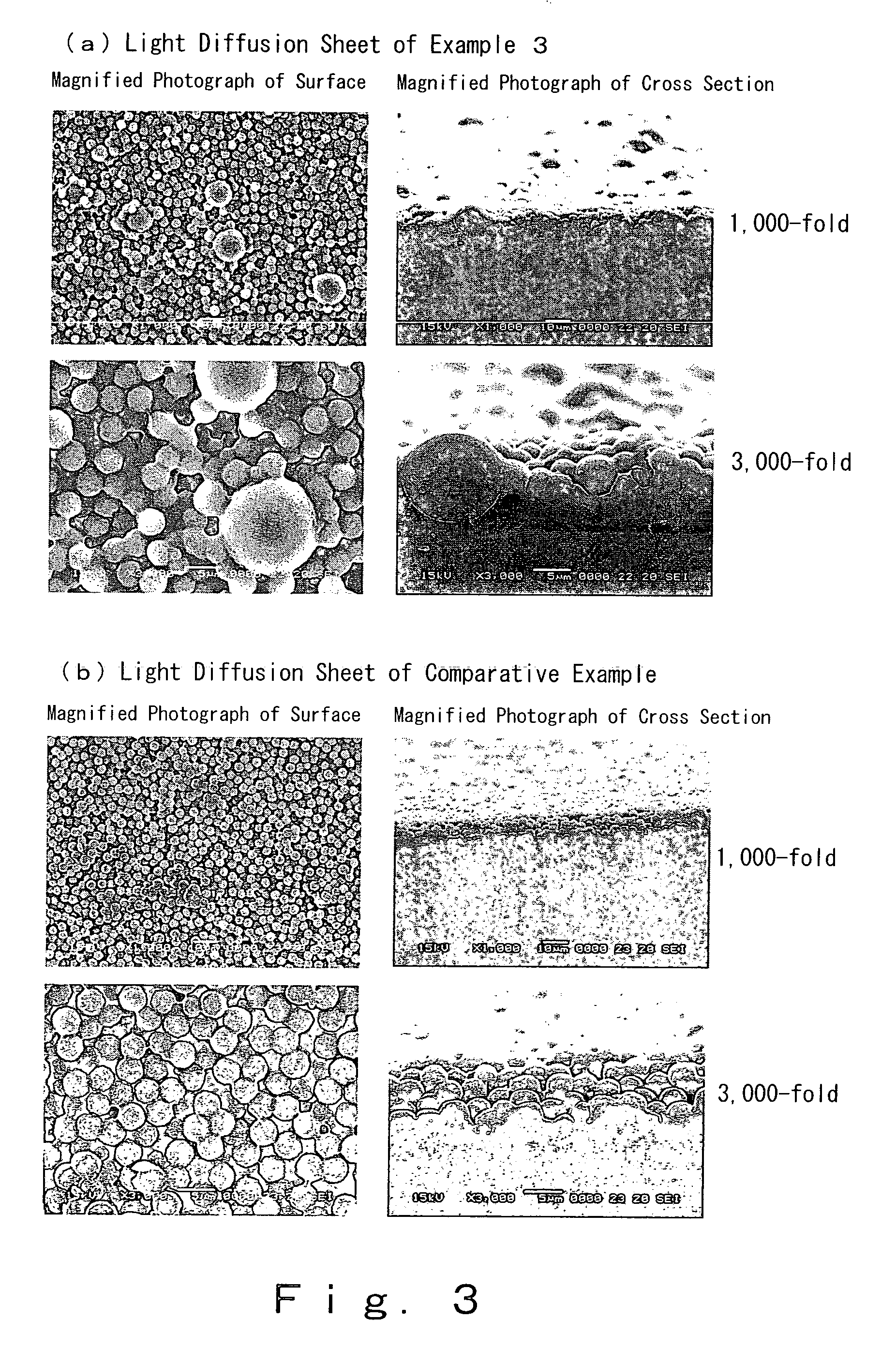
[0093] The present invention will be explained in detail below with reference to Examples, however, the present invention should not be construed as being limited to the description of the Examples.

example 1

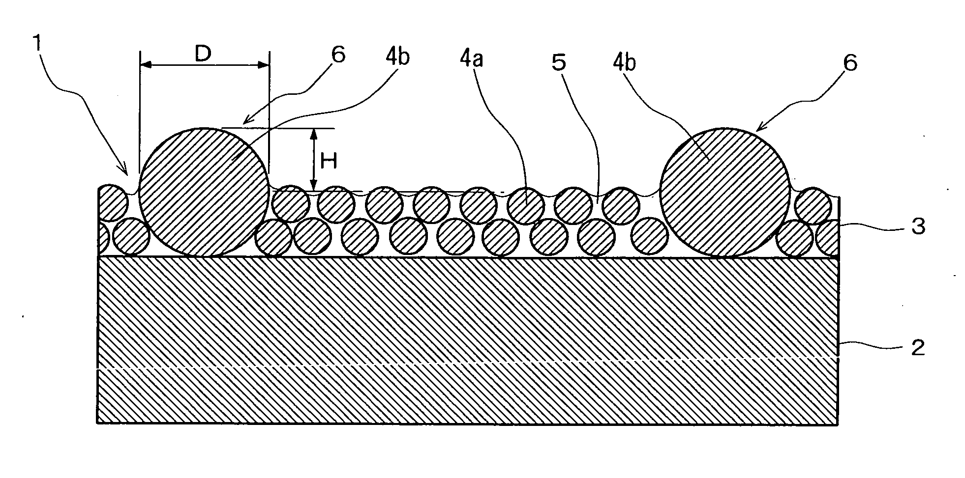
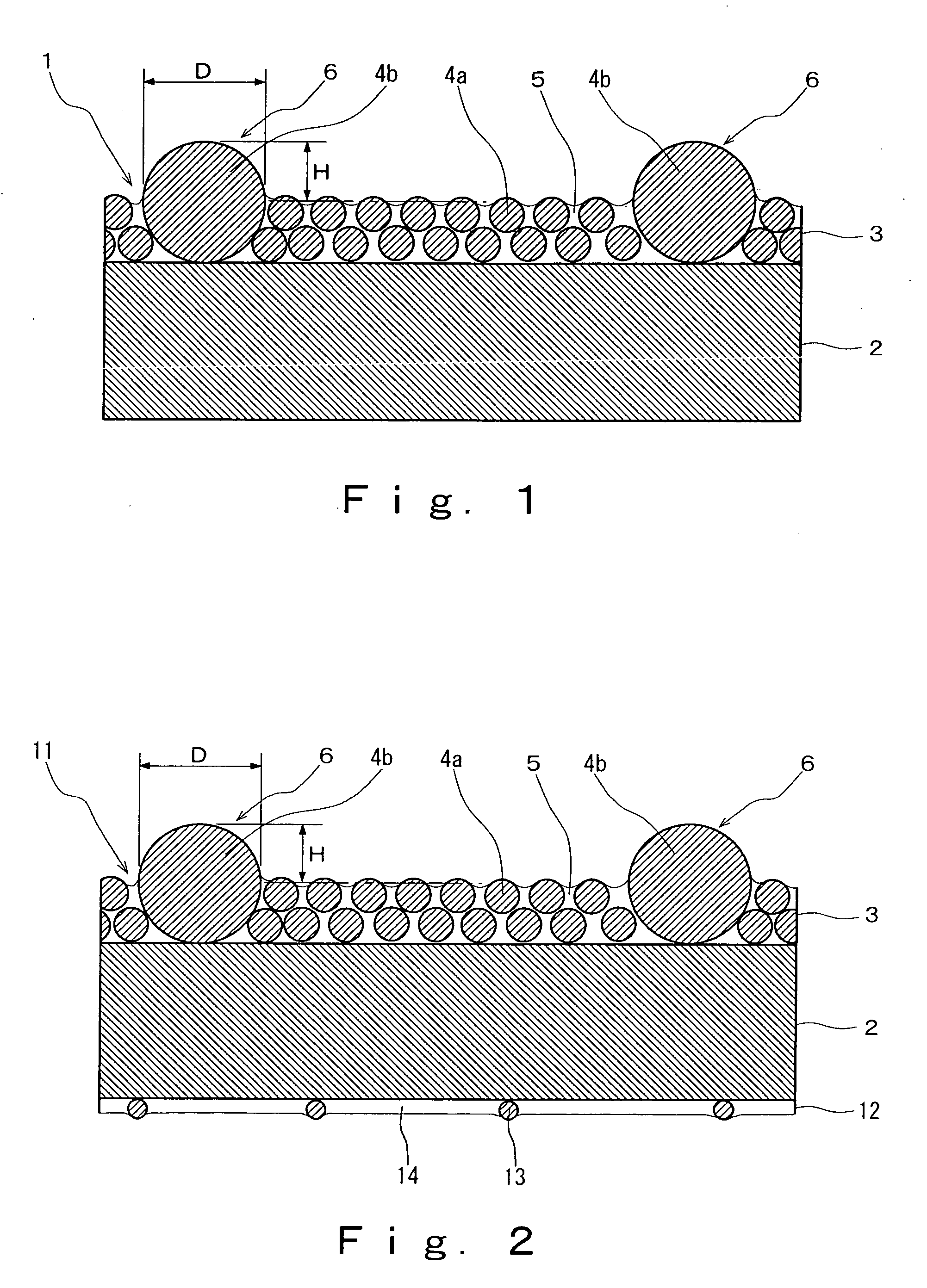
[0095] A light diffusion sheet of Example 1 was obtained in a similar manner to the above Comparative Example except that the small monodisperse beads and large beads were used as the beads after mixing. The used large beads were polydisperse beads having a mean particle size of 8.6 μm, a coefficient of variation of 33.5, and a particle size distribution width of 3.2 μm or greater and 23.8 μm or less. The weight ratio of the small monodisperse beads to the large beads was 95 / 5.

example 2

[0096] A light diffusion sheet of Example 2 was obtained in a similar manner to the above Comparative Example except that the small monodisperse beads and large beads were used as the beads after mixing. The used large beads were polydisperse beads having a mean particle size of 8.6 μm, a coefficient of variation of 33.5, and a particle size distribution width of 3.2 μm or greater and 23.8 μm or less. The weight ratio of the small monodisperse beads to the large beads was 9 / 1.


PUM


Abstract

An object of the present invention is to provide a light diffusion sheet having a favorable cost reduction capability due to excellent scratching preventive property of the front face, and having in addition thereto, a favorable directional light diffusion function, transmittivity of rays of light, and a thin film character; and a backlight unit capable of promoting performances such as luminance as well as price reduction, and thin and light modeling capability. The light diffusion sheet of the present invention has a light diffusion sheet including a transparent substrate layer, and a light diffusion layer overlaid on the front face side of the substrate layer, wherein the light diffusion layer has resin beads and a resin binder, characterized in that the light diffusion layer has protruding parts having a shape of a partial spherical body on the front face in a scattering manner. It is preferred that mean height of the protruding parts be 1 μm or greater and 10 μm or less, mean diameter of the protruding parts be 4 μm or greater and 18 μm or less, mean occupancy rate of the protruding parts be 2% or greater and 20% or less, and surface roughness (Ra) of the light diffusion layer be 1.5 μm or greater and 10 μm or less. As the beads, small monodisperse beads as a principal component, and large beads as a sub component may be included.

Description

BACKGROUND OF THE INVENTION [0001] 1. Field of the Invention [0002] The present invention relates to light diffusion sheets which have directional light diffusion function to allow transmitted rays of light to diffuse while collecting to a side in a normal direction and which are particularly suitable for a backlight of a liquid crystal display device, and backlight units in which the light diffusion sheet is used. [0003] 2. Description of the Related Art [0004] Liquid crystal display devices in widespread use have included a backlight system in which light emission is executed by irradiating onto a liquid crystal layer from the back face. In such a type of display devices, a backlight unit which is an edge light type, an immediate beneath type or the like is provided to an under face side of the liquid crystal layer. Such a backlight unit 50 of an edge light type is equipped with a rod-shaped lamp 51 for use as a light source, an optical waveguide plate 52 having a square plate sha...

Claims


Application Information

Patent Timeline
Patent Type & Authority Applications(United States)
IPC IPC(8): E01F9/04
CPCG02B5/0226G02B5/0278G02B6/0025Y10T428/24942Y10T428/24355Y10T428/24298Y10T428/24372G02F1/1335
Inventor YOSHIDA, MINORU
Owner KEIWA INCORPORATED
Why Eureka
Try Eureka