Trauma gage, kit and associated method

a technology of trauma gage and kit, applied in the field of orthopaedics, can solve the problems of complex devastating fractures, automobile accidents, trauma to long bones, etc., and achieve the effects of easy snapping the sleeve into place, facilitating the sleeve to remain constrained on the drill, and facilitating the sleeve to remain constrained

Inactive Publication Date: 2007-04-19
DEPUY PROD INC
View PDF23 Cites 7 Cited by
  • Summary
  • Abstract
  • Description
  • Claims
  • Application Information

AI Technical Summary

Benefits of technology

[0031] The technical advantages of the present invention further include the ability of the sleeve to remain constrained on the drill. When the sleeve is constrained on the drill the surgeon does not need to hold on to the sleeve. This permits the surgeon to perform other techniques on the patient. For example, according to another aspect of the present invention, the sleeve includes a snapping feature which, as the sleeve is inserted around the drill, the sleeve snaps into position on the drill. Th...

Problems solved by technology

These long bones are particularly exposed to trauma from accidents, and as such often are fractured during such trauma and may be subject to complex devastating fractures.
Automobile accidents, for instance, are a common cause. of trauma to long bones.
In particular, the femur and tibia ...

Method used


Image

  • Trauma gage, kit and associated method
  • Trauma gage, kit and associated method
  • Trauma gage, kit and associated method

Examples


Embodiment Construction

[0069] Embodiments of the present invention and the advantages thereof are best understood by referring to the following descriptions and drawings, wherein like numerals are used for like and corresponding parts of the drawings.

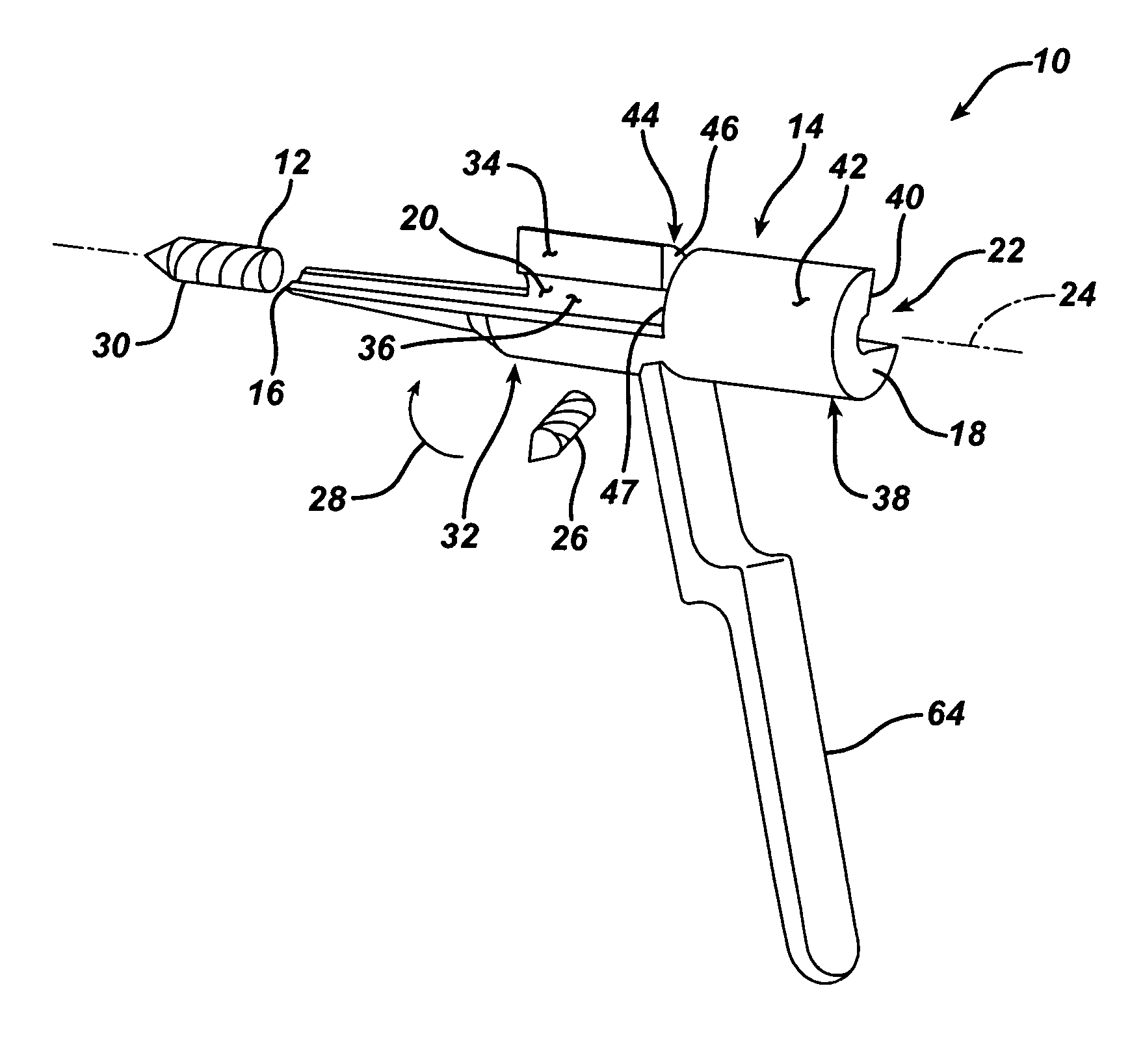
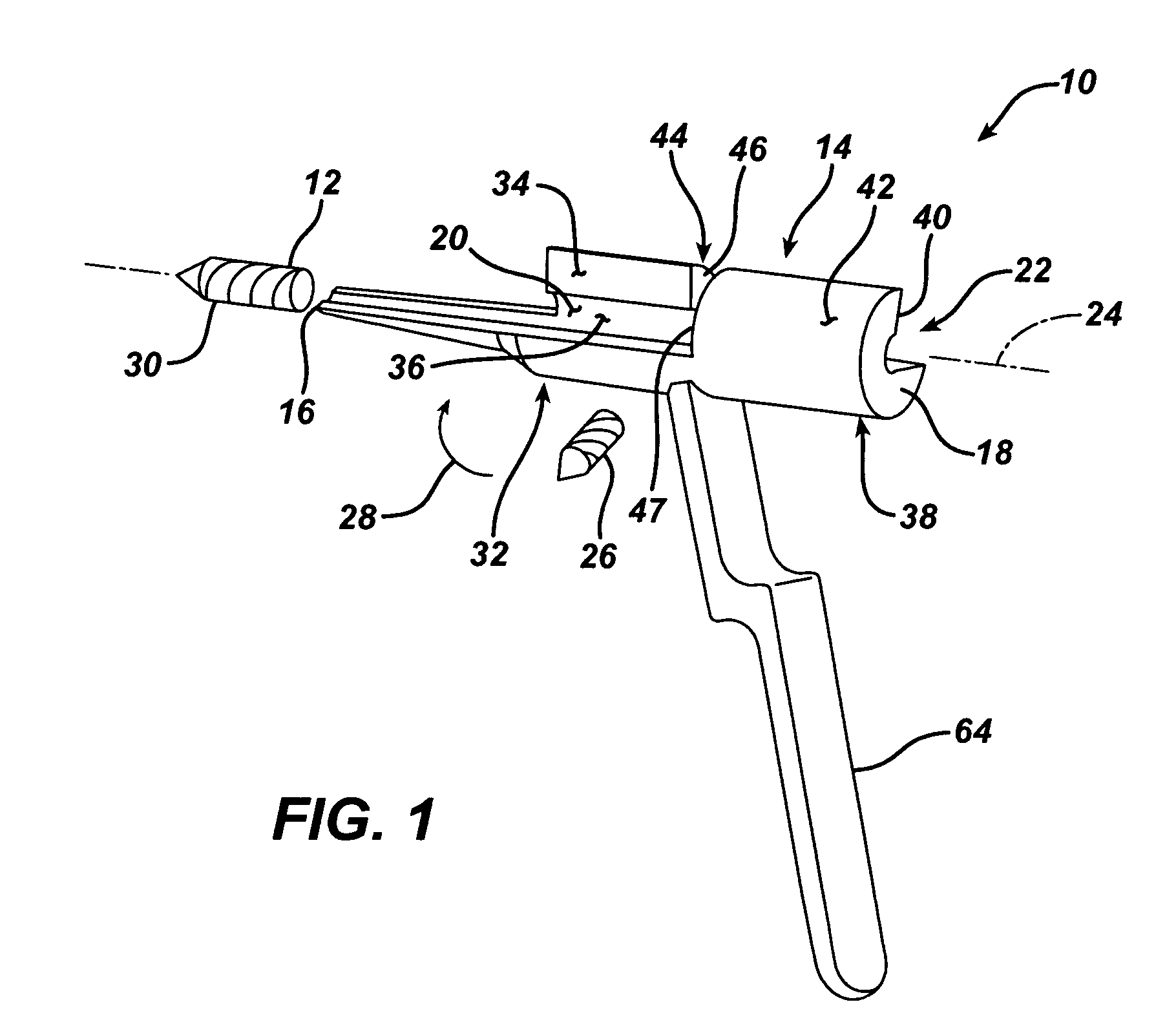
[0070] According to the present invention and referring now to FIG. 1, a depth gage 10 for use with a drill 12 in orthopedics is shown. The depth gage 10 includes a body 14. The body 14 defines a first end 16 as well as a second end 18 opposed to the first end 16. The body 14 further defines an inner periphery 20 defining a longitudinal aperture 22 through the body 14. The longitudinal aperture 22 is adapted for slidably receiving the drill 12. The longitudinal aperture 22 defines a longitudinal axis 24 of the longitudinal aperture 22. The body 14 is adapted to receive the drill 12 to be installed in the longitudinal aperture 22 in a direction non-coincident with the longitudinal axis 24. The body 14 is further adapted to restrain the drill 12 within the inn...


PUM


Abstract

A depth gage for use with a drill in trauma surgery is provided. The gage cooperates with the drill for measuring the depth of the drill in a long bone when implanting an intramedullary nail in a patient. The depth gage including a body. The body defines first and second ends opposed to each other and an inner periphery defining a longitudinal aperture through the body for slidably receiving the drill. The longitudinal aperture defines a longitudinal axis of the longitudinal aperture. The body is adapted to permit the drill to be installed into the longitudinal aperture in a direction non-coincident with the longitudinal axis.

Description

CROSS-REFERENCE TO RELATED APPLICATIONS [0001] Cross-reference is made to the following application: DEP 5417USNP titled “ORTHOPAEDIC GAGE, KIT AND ASSOCIATED METHOD” filed concurrently herewith which is incorporated herein by reference. TECHNICAL FIELD OF THE INVENTION [0002] The present invention relates generally to the field of orthopaedics, and more particularly, to a device for securing a prosthetic component to bone for use in orthopaedic trauma or orthopaedic joint products. BACKGROUND OF THE INVENTION [0003] The skeletal system includes many long bones that extend from the human torso. These long bones include the femur, fibula, tibia, humerus, radius and ulna. These long bones are particularly exposed to trauma from accidents, and as such often are fractured during such trauma and may be subject to complex devastating fractures. [0004] Automobile accidents, for instance, are a common cause. of trauma to long bones. In particular, the femur and tibia frequently fracture whe...

Claims


Application Information

Patent Timeline
IPC IPC(8): A61B17/60
CPCA61B17/1615A61B17/17A61B17/1725A61B2019/462A61B2090/062
Inventor RUHLING, MARC E.METZINGER, ANTHONY J.MOED, BERTON R.WATSON, J. TRACY
Owner DEPUY PROD INC
Why Eureka
Try Eureka