Passive wear-indicating sensor for implantable prosthetic device

a prosthetic device and wear-indicating sensor technology, applied in the direction of prosthesis, shoulder joints, applications, etc., can solve the problems of poor engine performance, affecting the performance of the device, damage to the contact surface, etc., and achieve the effect of improving the detection of wear indicating

Inactive Publication Date: 2007-04-19
MICROCHIPS INC
View PDF57 Cites 119 Cited by
  • Summary
  • Abstract
  • Description
  • Claims
  • Application Information

AI Technical Summary

Benefits of technology

[0019] In one embodiment, the method further includes, before the step of using a non-invasive imaging technique, a step of administering to the human or other animal a substance that interacts or binds with the wear indicating composition to enhance the detection of wear indicating composition that has been released from the prosthetic device. For example, the non-invasive imaging technique may be positron emission tomography and the substance may be a radioactive agent.

Problems solved by technology

In devices where two surfaces are in contact with, and moving with respect to, one another, friction and wear can damage the contacting surfaces and affect the performance of the device.
In automotive engines, for example, inadequate lubrication of the metal surfaces of the piston and cylinder can cause severe, irreversible damage to those surfaces and result in poor engine performance.
Similarly, particles present in the oil lubricating the piston and cylinder surfaces can scratch the contacting surfaces, ruining their smooth finish and adversely affecting performance.
Poor lubrication can result in small particles being formed by the two surfaces rubbing together (abrasion).
For example, in orthopedic implants, such as artificial joints, the implant is subjected to everyday motion, stress and strain.
This often leads to abrasion between different parts of the implant, and / or between the implant and the skeletal frame of the patient in whom the device is implanted.
The abrasion may generate wear debris particles in the area of the implant, and this debris can lead to serious complications.
The rubbing of the surface of the ball and the surface of the socket during normal use of the artificial hip can create abrasive wear debris or tiny particles of metal, ceramic, or polymer.
Similar wear problems may occur in other types of prosthetic implants, such as knee or spinal disc replacement.
This debris is problematic.
In particular, over time the debris can cause osteolysis, or local degradation of bone.
Osteolysis is a devastating problem because local bone erosion can quickly weaken the bone remaining after the implantation of an orthopedic prosthesis, causing implant loosening, or a sudden bone or implant fracture.
On the other hand, it is highly undesirable to have to perform invasive surgery in order to evaluate the condition of the implant.
Such invasive surgery is not only time consuming, but also costly and painful to the patient.
Currently available detection techniques, however, are crude, invasive, and / or imprecise.
The presence of friction / abrasion at the articulating surfaces of a prosthetic implant also can present difficulties in the delivery of drug at the joint.
Common drug delivery systems, including polymer coatings and conventional depots, cannot be used in joints due to the mechanical and abrasive forces present in the joint.

Method used


Image

  • Passive wear-indicating sensor for implantable prosthetic device
  • Passive wear-indicating sensor for implantable prosthetic device
  • Passive wear-indicating sensor for implantable prosthetic device

Examples


Embodiment Construction

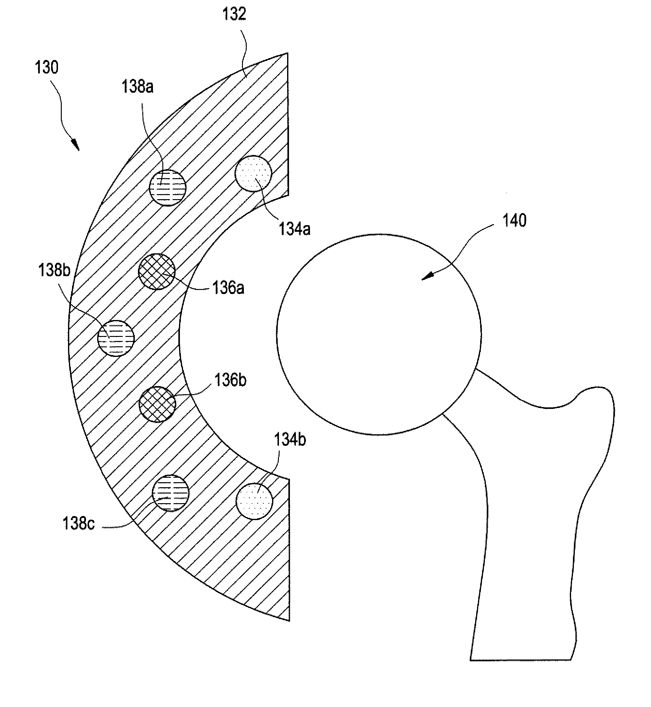
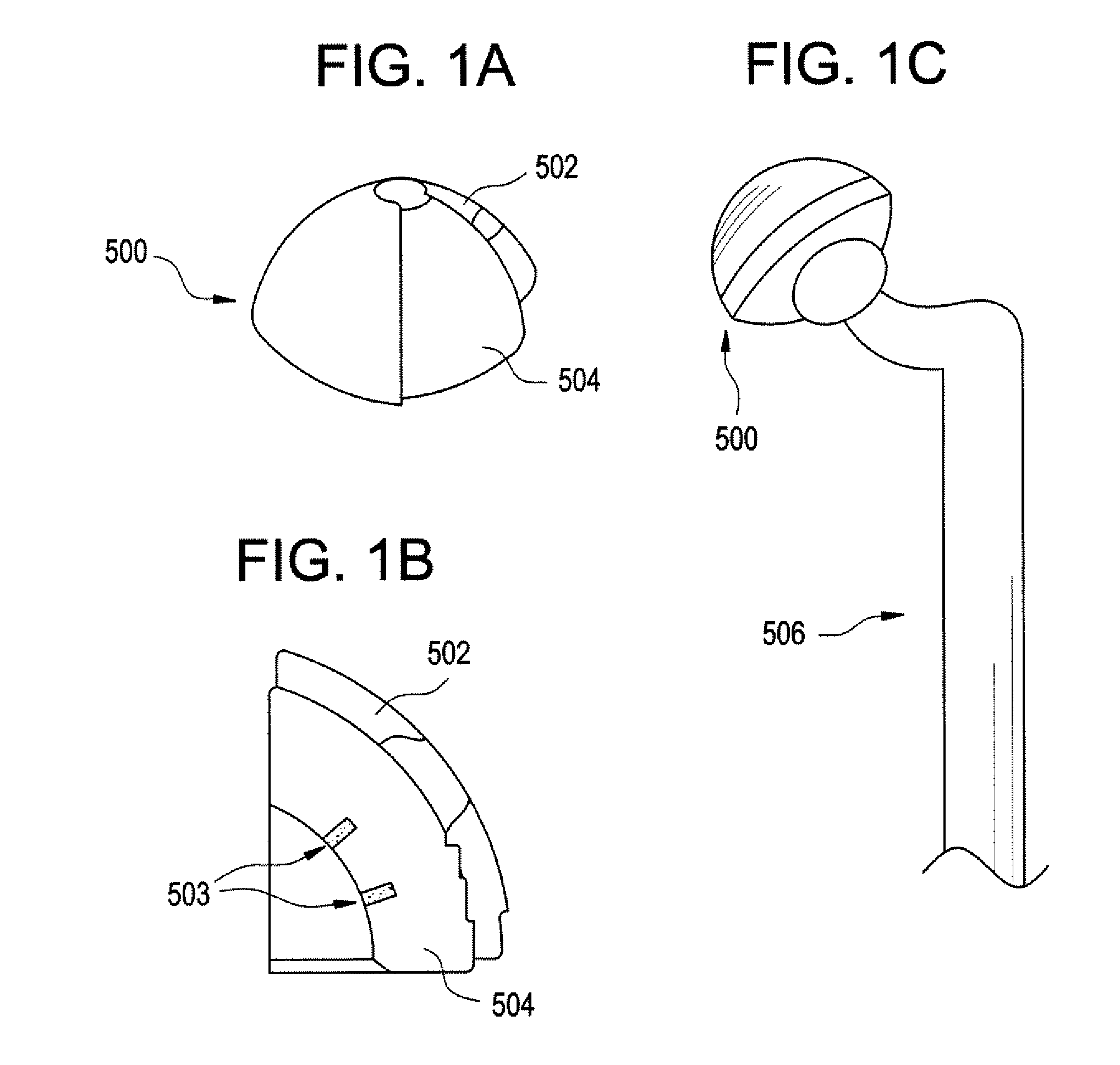
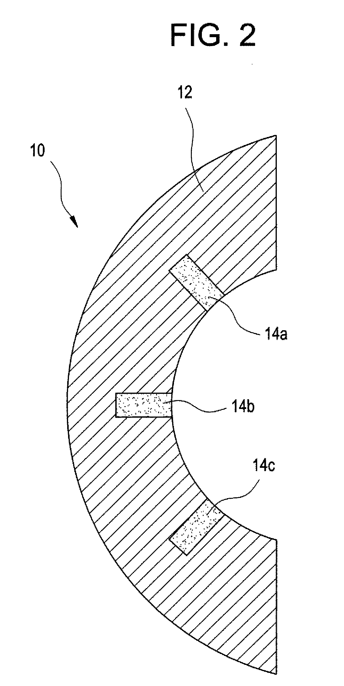
[0045] Methods and devices have been developed that utilize an abrasion mechanism for the non-invasive detection of medical implant device wear and / or for drug delivery to a joint space. In addition, the methods and devices can be adapted for the detection of device wear or the release of chemicals in non-medical applications, such as the detection of wear or release of molecules in automotive, watercraft, or aircraft parts. The released particles can be a wear indicating material (e.g., a diagnostic agent) or can be a therapeutic or prophylactic agent (e.g., an active pharmaceutical agent or API formulation).

[0046] Advantageously, this wear sensor can be “passive,” in the sense that the means for indicating wear requires no electrical or electromechanical component as part of the implant device itself. Release of the indicator material is triggered without electrical power. This beneficially can reduce the cost and complexity of the device, yet can enable the physician to non-inva...


PUM

PropertyMeasurementUnit
volumeaaaaaaaaaa
volumeaaaaaaaaaa
volumeaaaaaaaaaa

Abstract

A method is provided for non-invasively detecting mechanical wear of a prosthetic device implanted in a patient, the method comprises using a non-invasive imaging technique to image the prosthetic device that includes a wear indicating composition; and detecting whether the wear indicating composition has been released from the prosthetic device, and, if so, the location, type, and/or amount thereof. The implant device includes a prosthetic device body having at least one outer surface area; at least one reservoir (e.g., a plurality of discretely spaced micro-reservoirs) in the device body; a wear indicator composition disposed in said at least one reservoir, wherein mechanical wear of the at least one outer surface area of the device body in vivo causes release of at least part of the wear indicator composition. The prosthetic device body may be one for replacement of a hip, a knee, a shoulder, an elbow, or a vertebra.

Description

CROSS-REFERENCE TO RELATED APPLICATION [0001] This application claims the benefit of U.S. Provisional Application No. 60 / 726,937, filed Oct. 14, 2005. The application is incorporated herein by reference in its entirety.BACKGROUND OF THE INVENTION [0002] This invention is generally in the field of sensors and non-invasive means for detecting mechanical wear of devices, such as medical devices for implantation into a human or animal patient, including but not limited to orthopedic and dental prosthetic implants. [0003] In devices where two surfaces are in contact with, and moving with respect to, one another, friction and wear can damage the contacting surfaces and affect the performance of the device. In automotive engines, for example, inadequate lubrication of the metal surfaces of the piston and cylinder can cause severe, irreversible damage to those surfaces and result in poor engine performance. Similarly, particles present in the oil lubricating the piston and cylinder surfaces...

Claims


Application Information

Patent Timeline
Patent Type & Authority Applications(United States)
IPC IPC(8): A61F2/30A61F2/28A61B6/12
CPCA61B5/055A61B6/037A61B5/4528A61B6/481A61B8/481A61F2/32A61F2/34A61F2/36A61F2/38A61F2/3804A61F2/3859A61F2/389A61F2/40A61F2/4425A61F2/4657A61F2002/2817A61F2002/30004A61F2002/30062A61F2002/30075A61F2002/30113A61F2002/30154A61F2002/30156A61F2002/30326A61F2002/30673A61F2002/30677A61F2002/30682A61F2002/30733A61F2002/30787A61F2002/3081A61F2002/30838A61F2002/30878A61F2002/30884A61F2002/30904A61F2002/30971A61F2002/3401A61F2002/3456A61F2002/3469A61F2002/3495A61F2002/3611A61F2002/3625A61F2002/4662A61F2002/488A61F2210/0004A61F2210/0061A61F2230/0006A61F2230/0021A61F2230/0023A61F2250/0014A61F2250/0037A61F2310/00011A61F2310/00179A61L27/50A61B5/4514A61F2/488
Inventor CIMA, MICHAEL J.SANTINI, JOHN T. JR.SHELTON, KURTPRESCOTT, JAMES H.STAPLES, MARK A.COPPETA, JONATHAN R.
Owner MICROCHIPS INC
Why Eureka
Try Eureka