Installation construction method for boiler facilities

a construction method and boiler technology, applied in the field of installation construction methods of boiler facilities, can solve the problems of increased risk of workplace accidents and high construction costs, and achieve the effects of improving work efficiency, improving work safety, and convenient carrying in an installed position

Inactive Publication Date: 2007-04-26
MITSUBISHI HITACHIPOWER SYST LTD
View PDF2 Cites 5 Cited by
  • Summary
  • Abstract
  • Description
  • Claims
  • Application Information

AI Technical Summary

Benefits of technology

[0031] With the present invention, as described above, the various types of equipment and accessory members to be installed within the boiler building are carried in and installed while building the boiler building, so the columns and beams of the boiler building pose little obstruction, and accordingly the various types of equipment and accessory members can be easily carried in an installed. Also, construction of the boiler building and carrying in and installation of the various types of equipment and accessory members are performed in parallel, thereby improving work efficiency.
[0032] Moreover, a great part of the various types of equipment and accessory members to be installed within the boiler building can be assembled near the ground rather than at high places, and can be directly assembled by crane as with the steel structure, so work safety can be improved, and costs can be reduced due to standardization of work amount during the construction schedule and improved work efficiency.

Problems solved by technology

This means that the work of carrying in and installing various types of equipment and accessories is concentrated in the period following completion of the boiler building, leading to problems in that all work regarding ducts, piping, and so forth, is high-place work, meaning deterioration in work capability, and in that work within a limited space means work is restricted, requiring a longer construction schedule, and further that the amount of high-risk work at high places is great, leading to higher construction costs, and increased risk of workplace accidents.
Also, with arrangements wherein multiple members are combined to form a unit, and these are hoisted above the installation location using a crane and the lower for installation, already-assembled beams and columns and the like tend to interfere with carrying in and installing the units.

Method used


Image

  • Installation construction method for boiler facilities
  • Installation construction method for boiler facilities
  • Installation construction method for boiler facilities

Examples


Embodiment Construction

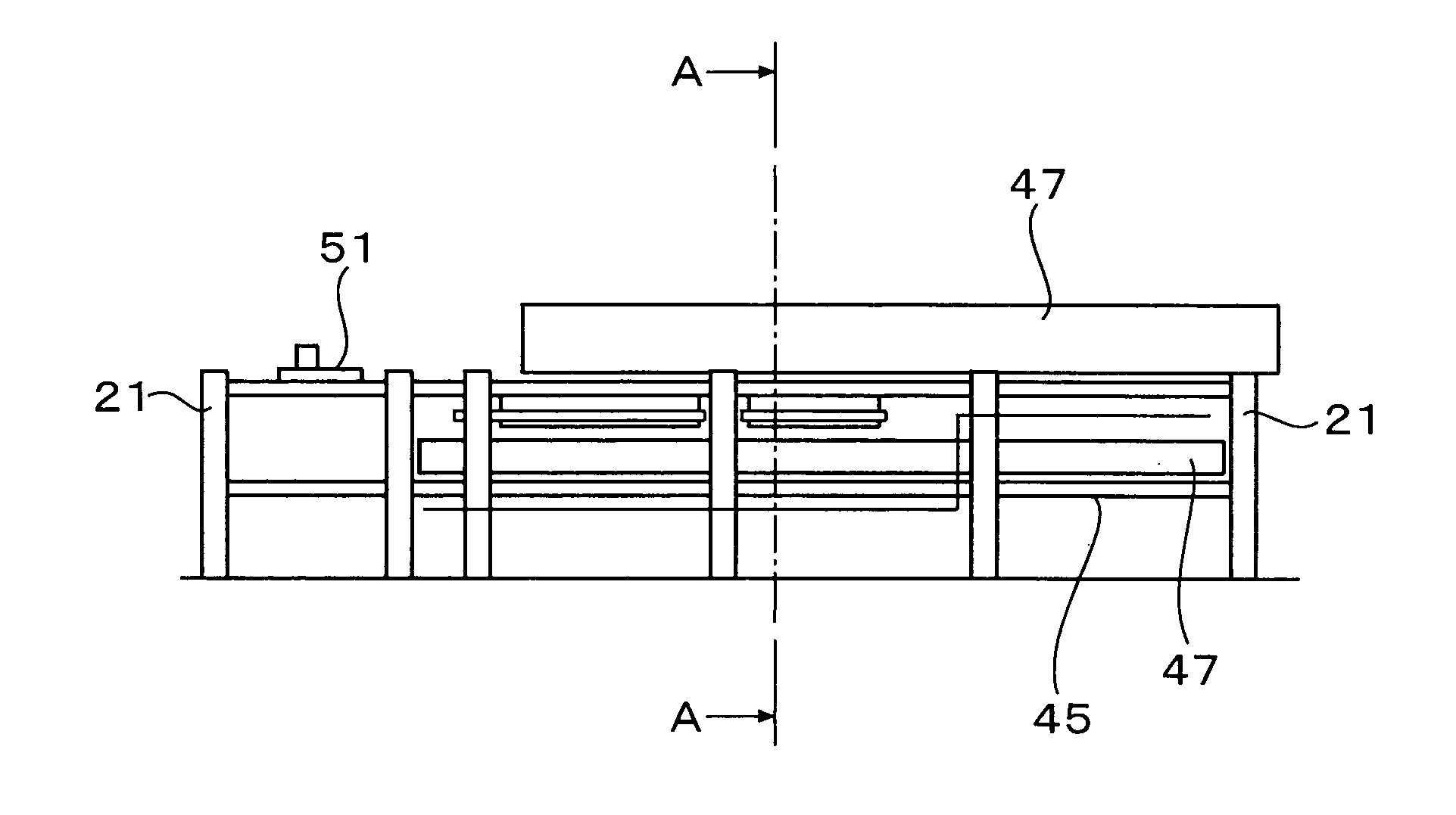
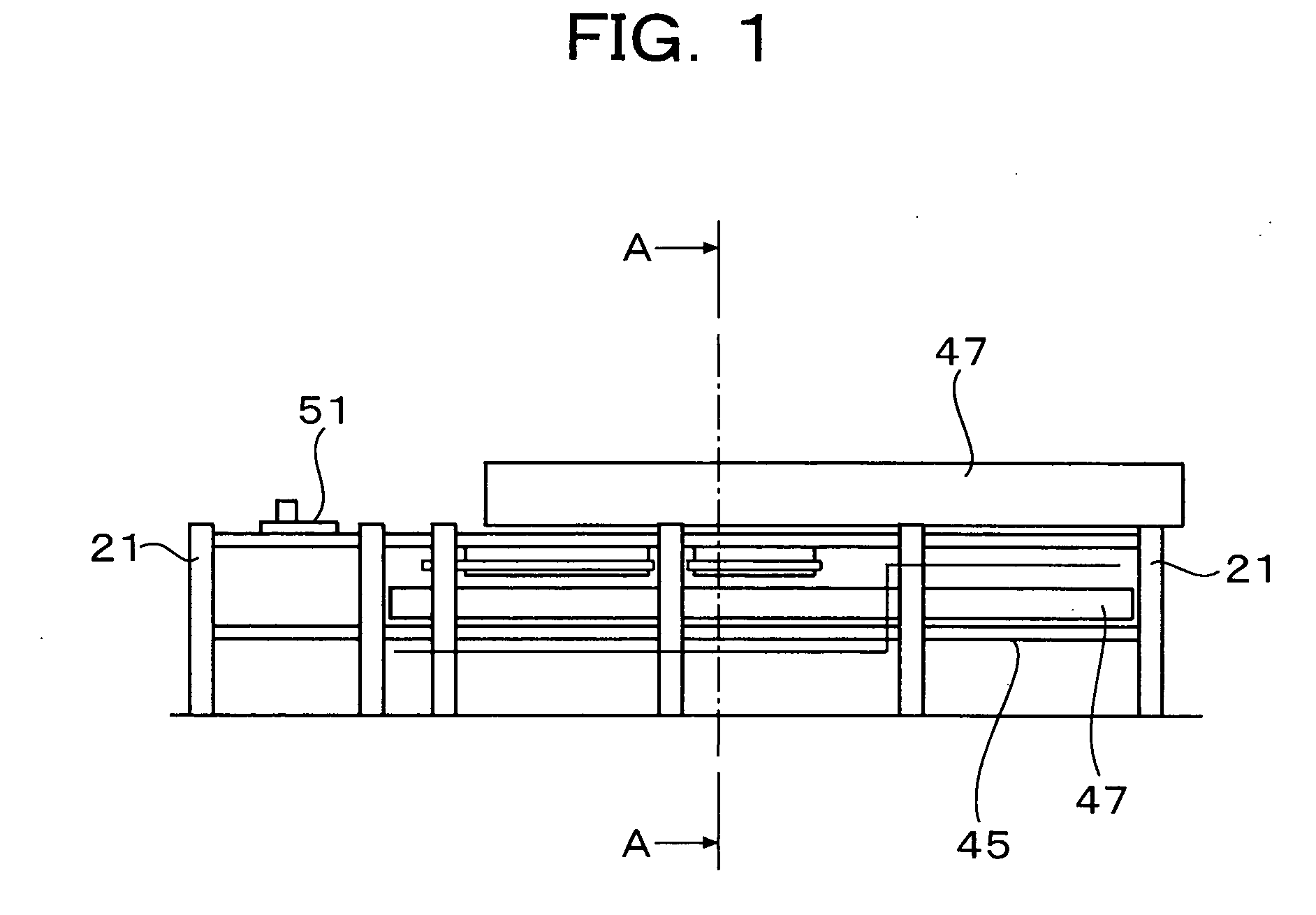
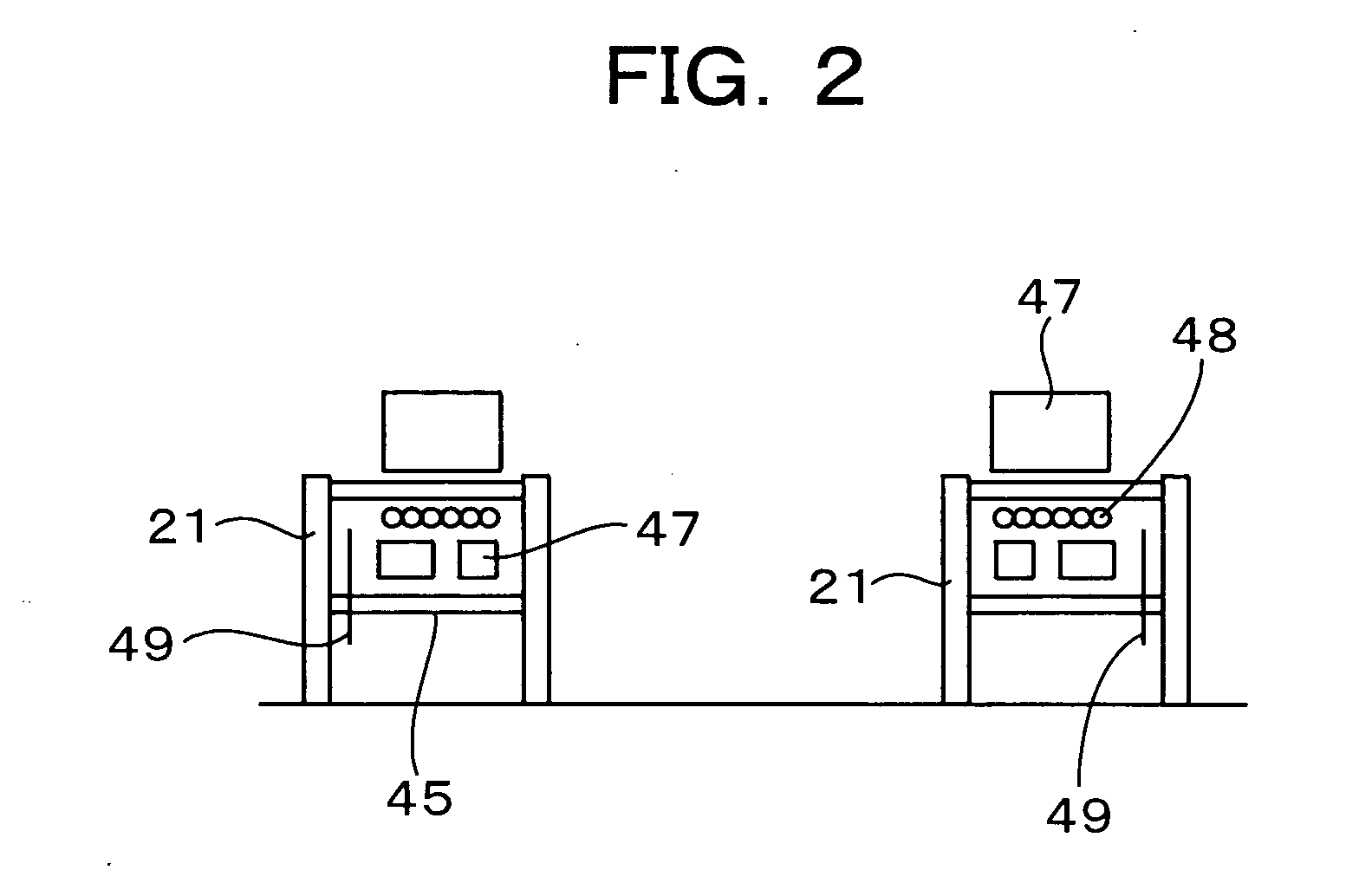
[0062] Next, an embodiment of the present invention will be described, with reference to the drawings. FIGS. 1 through 10 are schematic configuration diagrams for describing the boiler facilities installation construction method according to the present embodiment. In these drawings, FIGS. 2, 4, 6, 8, and 10, are views taken along line A-A in FIGS. 1, 3, 5, 7, and 9, respectively. Also, FIGS. 11 through 18 are perspective views illustrating the state at the time of installing the boiler facilities.

[0063] First, as shown in FIGS. 1 and 2, a predetermined number of first-level steel columns 21 are assembled, and in conjunction therewith, a first floor unit 45 is disposed between the first-level steel columns 21. FIG. 11 illustrates the state of assembling the first-level steel columns 21 by a crane 46.

[0064] The steel structure is made up of columns and beams, which are fastened at the joints thereof with, for example, L-shaped fasteners and bolts. The columns are vertically divided...


PUM

PropertyMeasurementUnit
thermalaaaaaaaaaa
lengthaaaaaaaaaa
shapeaaaaaaaaaa

Abstract

An installation construction method is provided for boiler facilities in which the boiler facilities include a boiler building configured of a steel structure, a boiler main unit to be installed within the boiler building, various types of equipment to be installed to the boiler main unit, and accessory members which are accessory thereto. During construction of the boiler building, the various types of equipment and the accessory members are carried into the boiler building and installed.

Description

BACKGROUND OF THE INVENTION [0001] 1. Field of the Invention [0002] The present invention relates an installation construction method for boiler facilities, and particularly relates to an installation construction method for improving work efficiency and safety in the installation of the various types of equipment disposed within a steel structure building and accessory members accessory thereto. [0003] 2. Description of the Related Art [0004]FIG. 19 is a schematic configuration diagram of a common boiler facility for electric power production. A boiler main unit 1 is disposed within a boiler building 3 configured of a steel structure 2 around and above, and is suspended from top girders traversing the top of the boiler building 3 by sling bolts. [0005] Secondary air for combustion to the boiler main unit 1 is guided to a furnace combustion chamber with a burner, via a forced draft fan, an air pre-heater 5, a wind box 6, and so on forth. Also, coal fuel transporting air is guided fr...

Claims


Application Information

Patent Timeline
Patent Type & Authority Applications(United States)
IPC IPC(8): B23P21/00B21D51/16
CPCE04H5/02F22B37/24Y10T29/49345Y10T29/49387Y10T29/49904Y10T29/4935
Inventor KAWASHIMA, HIROKIMASAKI, TOSHIHIROKAWASHIMA, YASUAKITATEHIRA, KAZUKI
Owner MITSUBISHI HITACHIPOWER SYST LTD
Why Eureka
Try Eureka