Imaging system with anesthesia system

Inactive Publication Date: 2007-04-26
XENOGEN CORP
View PDF32 Cites 9 Cited by
  • Summary
  • Abstract
  • Description
  • Claims
  • Application Information

AI Technical Summary

Benefits of technology

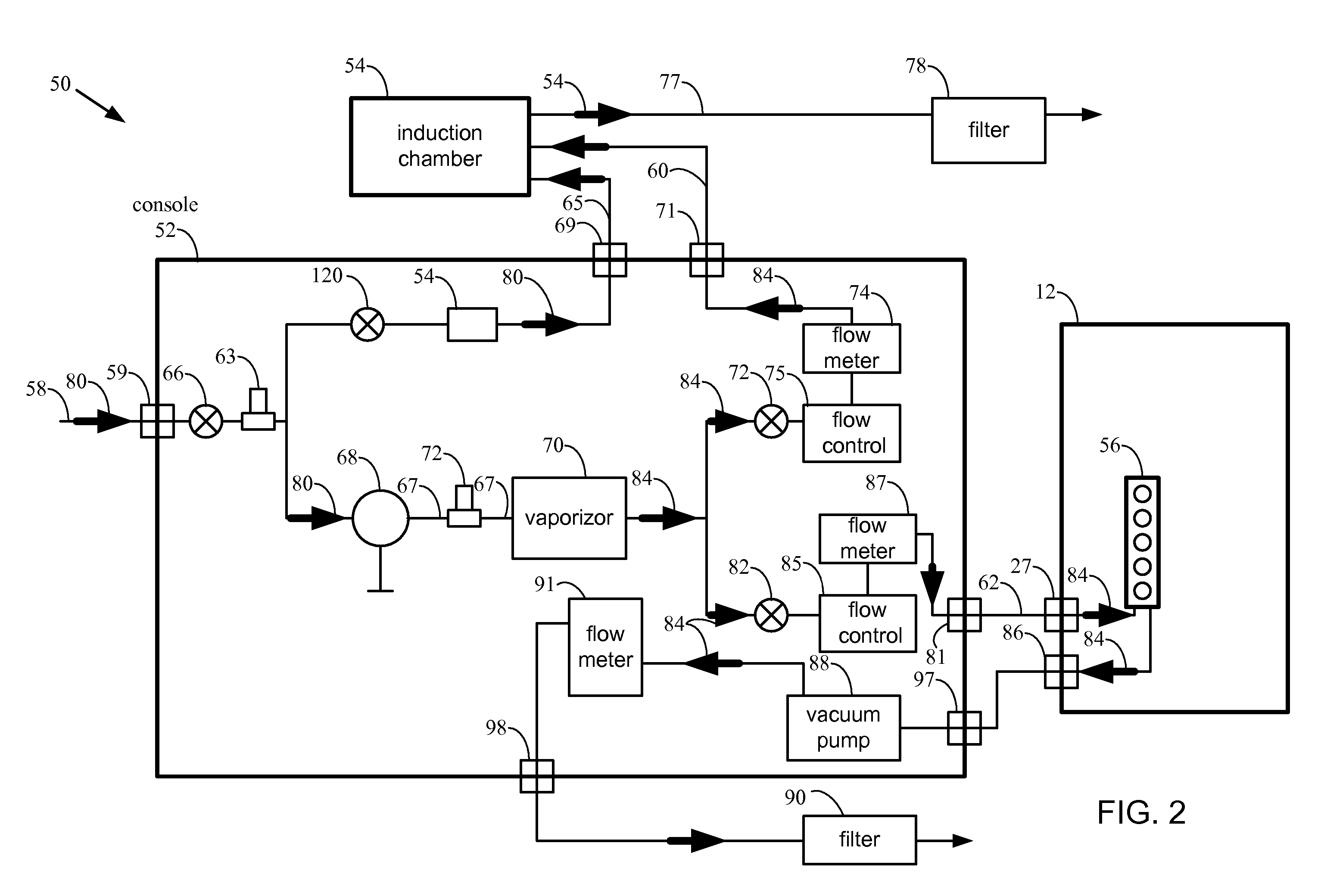
[0012] In yet another aspect, the present invention relates to a gas delivery device capable of providing anesthesia gas and oxygen to multiple living specimens. The gas delivery device comprises an inlet for receiving anesthesia gas and oxygen, multiple specimen interface

Problems solved by technology

This is in contrast to prior art systems comprising general flow control and binary on/

Method used


Image

  • Imaging system with anesthesia system
  • Imaging system with anesthesia system
  • Imaging system with anesthesia system

Examples


Embodiment Construction

[0023] In the following detailed description of the present invention, numerous specific embodiments are set forth in order to provide a thorough understanding of the invention. However, as will be apparent to those skilled in the art, the present invention may be practiced without these specific details or by using alternate elements or processes. In other instances well known processes, components, and designs have not been described in detail so as not to unnecessarily obscure aspects of the present invention.

I. Imaging System

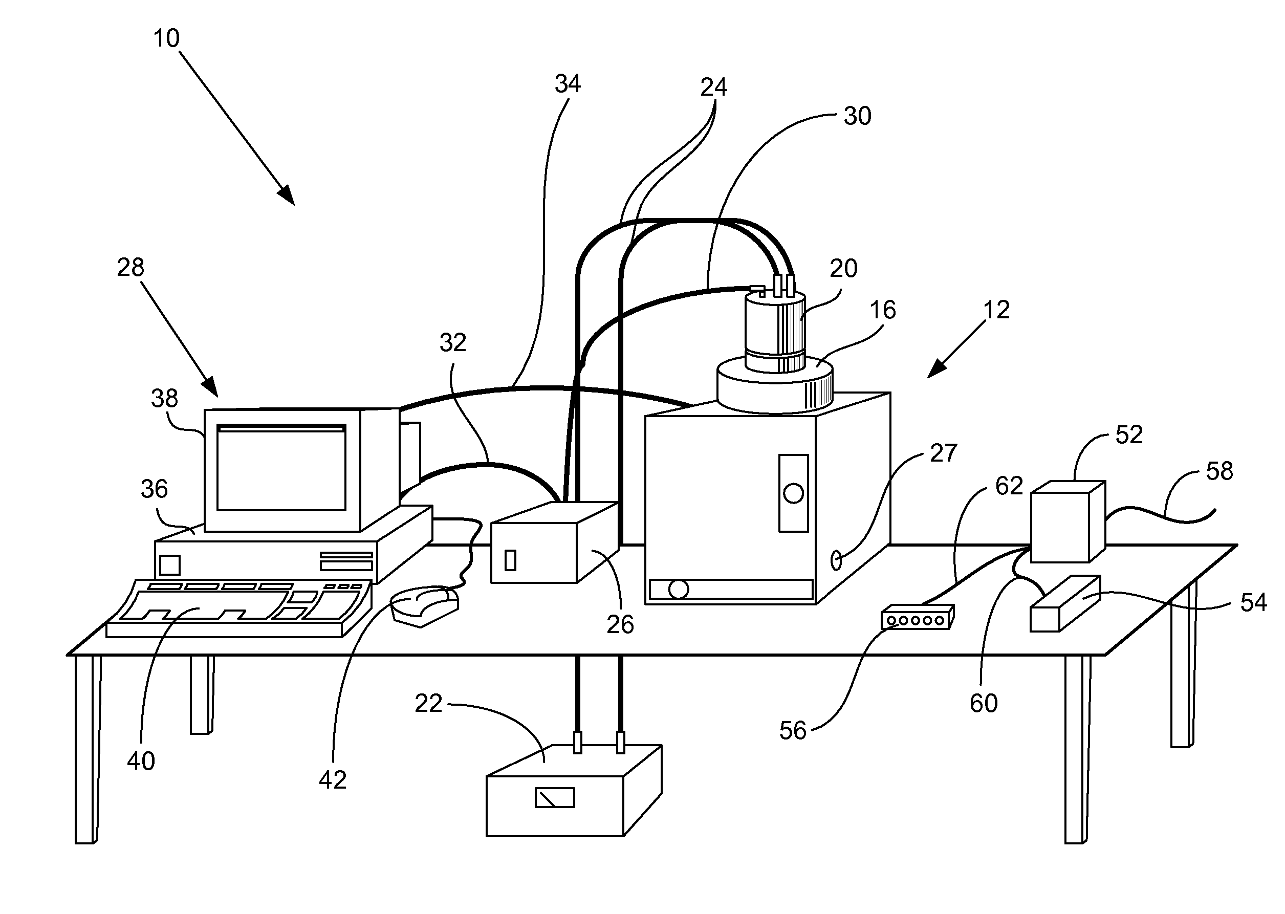
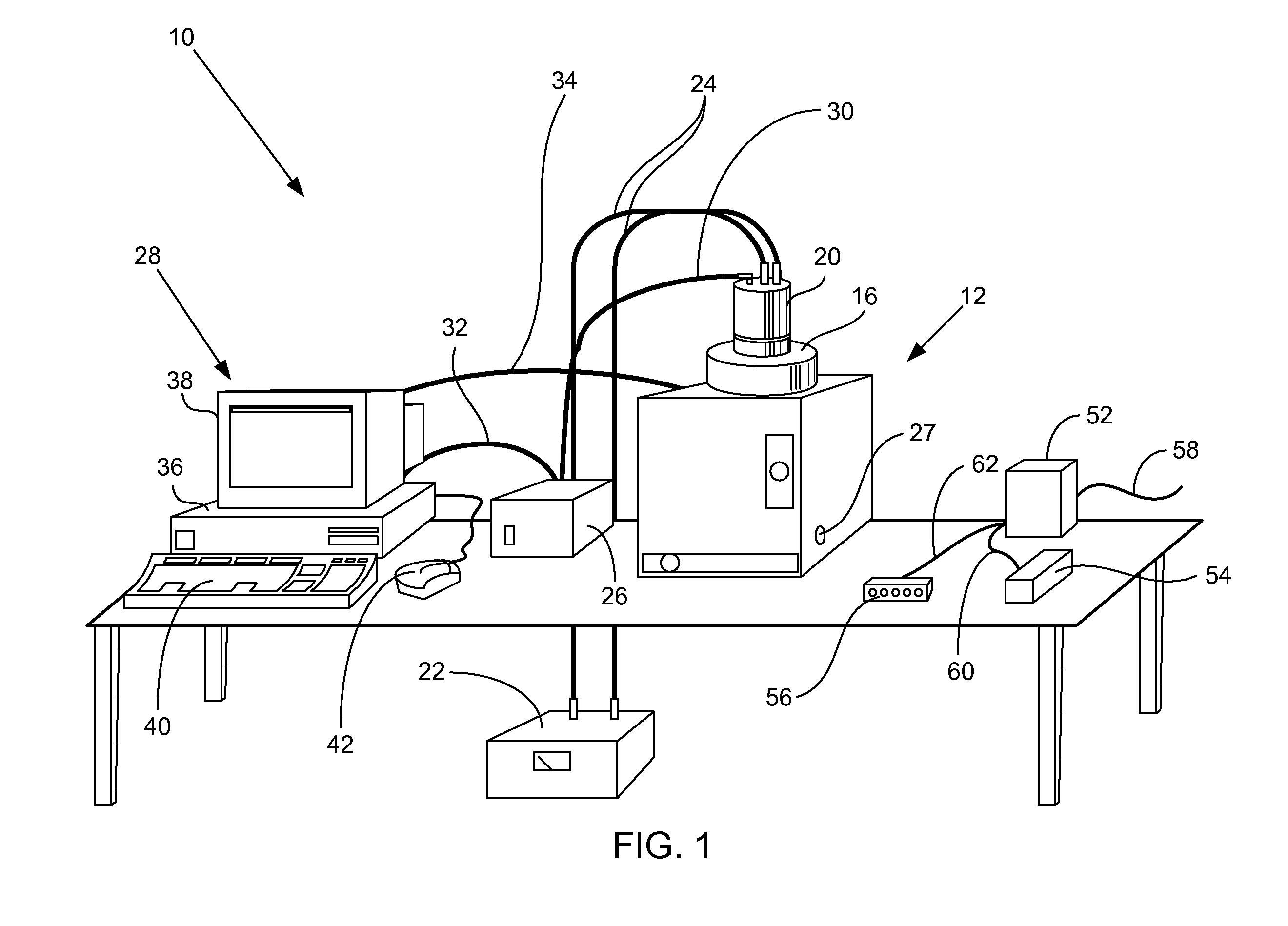
[0024] In one aspect, the present invention relates to imaging systems for capturing an image of a low intensity light source. FIG. 1 illustrates an imaging system 10 configured to capture photographic and luminescence images in accordance with one embodiment of the present invention. Imaging system 10 may be used for imaging a low intensity light source, such as luminescence from luciferase-expressing cells, fluorescence from fluorescing molecules, and t...


PUM


Abstract

The present invention provides improved anesthesia delivery systems that consistently and reliably deliver anesthesia gas to multiple gas outlets. The systems are particularly useful for anesthetizing multiple mammals and living specimens to be imaged by a low-light level imaging system. The anesthesia delivery systems are suitable for use with conventional oxygen sources, and convert the high pressures associated with a conventional oxygen source to lower pressures suitable for use with small mammals and suitable for combination with an anesthesia gas at low flow rates. The systems include an anesthesia gas source that combines anesthesia gas with the oxygen. The combination of anesthesia gas and oxygen is supplied to one or more multiple outlets.

Description

CROSS-REFERENCE TO RELATED APPLICATIONS [0001] This application claims priority under U.S.C. §120 from co-pending U.S. patent application Ser. No. 10 / 081,040, filed Feb. 20, 2002 and entitled, “Multiple Output Anesthesia System”, which is incorporated herein for all purposes. FIELD OF THE INVENTION [0002] The present invention relates generally to anesthesia delivery systems. In particular, the present invention relates to anesthesia systems for use with living specimen imaging applications. BACKGROUND OF THE INVENTION [0003] One new and specialized type of imaging involves the capture of low intensity light—often on the order of only tens to hundreds of photons—from a light-emitting sample. The low intensity light source may be emitted from any of a variety of light-emitting sources within a living specimen, e.g., luciferase expressing cells within a mammalian specimen. The source of the light indicates portions of the sample, such as traced molecules in a particular portion of a l...

Claims


Application Information

Patent Timeline
IPC IPC(8): A61M15/00A61D7/04A01K1/03A22B3/00A61M16/00A61M16/01A61M16/10A61M16/18A61M16/20
CPCA01K1/031A22B3/00A22B3/005A61M16/104A61M16/18A61M2016/0039A61D7/04A61M16/202A61M16/209
Inventor DALGETTY, RICHARD G.BATES, BRIAN R.NELSON, MICHAEL B.
Owner XENOGEN CORP
Why Eureka
Try Eureka