Tensioner lever

a technology of a tensioner and a sleeve, which is applied in the direction of gearing details, belts/chains/gears, gearing details, etc., can solve the problems of surface wear or seizure, and achieve the effect of reducing friction loss in the pivot part made up of the pivotal support boss and the slide bearing member, high durability and productivity

Active Publication Date: 2020-11-19
TSUBAKIMOTO CHAIN CO
View PDF0 Cites 5 Cited by
  • Summary
  • Abstract
  • Description
  • Claims
  • Application Information

AI Technical Summary

Benefits of technology

[0014]The tensioner lever of the present invention includes a slide bearing member made of a synthetic resin that covers the inner circumferential surface of the pivotal support boss, so that, with the slide bearing member interposed between the shoulder bolt that functions as the pivot axis and the high-rigidity pivotal support boss, contact between the pivotal support boss and the shoulder bolt is avoided, and wear or seizure caused by friction between the pivotal support boss and the shoulder bolt is inhibited. Namely, friction loss in the pivot part made up of the pivotal support boss and slide bearing member can be reduced, as a result of which high durability is achieved. Moreover, the slide bearing member is made of the same synthetic resin as the shoe, and the slide bearing member and the shoe are configured as a continuous one-piece component connected together by the connecting part. These are integrally formed by double injection molding in the production process of the tensioner lever, so that it is not necessary to mold a slide bearing member separately from the lever body and then to assemble it to the lever body. Since the slide bearing member is formed and assembled at the same time as the molding of the shoe, a level of productivity equivalent to that of an existing tensioner lever for which the shoe and lever body are integrally formed by double injection molding can be achieved, and thus production cost can be reduced.
[0015]According to the configuration set forth in claim 2 of the present invention, the connecting part is provided such as to be exposed at least on one side face of the lever body. This feature ensures that the synthetic resin material reliably flows in during the double injection molding to form the connecting part and slide bearing member to achieve high productivity, and allows easy formation of an oil guide groove in the connecting part if such groove is to be provided.
[0016]According to the configuration set forth in claim 3 of the present invention, the continuous one-piece component including the slide bearing member, the shoe, and the connecting part includes an oil guide groove that extends from the traveling surface of the shoe to the slide bearing member that covers the inner circumferential surface of the pivotal support boss. This feature allows engine oil to be reliably supplied to the inner circumferential surface of the slide bearing member inside the pivotal support boss from the traveling surface of the shoe. As the engine oil serving as lubricant can be uniformly introduced and permeated between the slide bearing member and the shoulder bolt, localized wear, friction loss, or seizure resulting from contact between the slide bearing member and the shoulder bolt can be further retarded, so that higher durability can be achieved. If the oil guide groove is made of polyamide resin containing polytetrafluoroethylene, the low-friction properties of the resin ensure smooth supply of engine oil to the slide bearing member. The engine oil provides a cooling effect to suppress heat generation in the pivot part, so that the possibility of seizure can be reduced even more.
[0017]According to the configuration set forth in claim 4 of the present invention, the oil guide groove includes an oil collecting part provided on the traveling surface of the shoe. This feature ensures that engine oil present on the traveling surface of the shoe to be collected so that the engine oil can be readily supplied to the inner circumferential surface of the slide bearing member via the oil guide groove.
[0018]According to the configuration set forth in claim 5 of the present invention, a flange part on one side of the pivotal support boss includes a cut-away portion that accelerates oil introduction radially from outside to inside of the slide bearing member. This feature allows the engine oil supplied by the oil guide groove to be readily delivered to the inner circumferential surface of the slide bearing member.
[0019]According to the configuration set forth in claim 6 of the present invention, the lever body is made of a polyamide resin containing glass fiber reinforcement, while the shoe, the slide bearing member, and the connecting part are made of a polyamide resin containing polytetrafluoroethylene. This ensures that, while the lever body has high rigidity, the inner circumferential surface of the pivotal support boss can be imparted with good low-friction properties, so that friction loss in the pivot part can be reduced. Even when there is no oil film on the inner circumferential surface of the slide bearing member, the low-friction properties of the material itself of the slide bearing member, which is made of polyamide resin containing polytetrafluoroethylene, can ensure rotatability of the tensioner lever while reducing the friction loss in the pivot part.

Problems solved by technology

Since the lever body of the tensioner lever including the pivotal support boss is made of a high-rigidity material such as nylon resin containing glass fiber reinforcement to secure strength, making the lever body swingable around the pivot axis by passing a shoulder bolt through the through hole of the pivotal support boss entails a problem of possible wear or seizure on the surface of the pivotal support boss contacting the shoulder bolt, i.e., the inner circumferential surface of the pivotal support boss, due to friction.

Method used


Image

  • Tensioner lever
  • Tensioner lever
  • Tensioner lever

Examples


embodiment 1

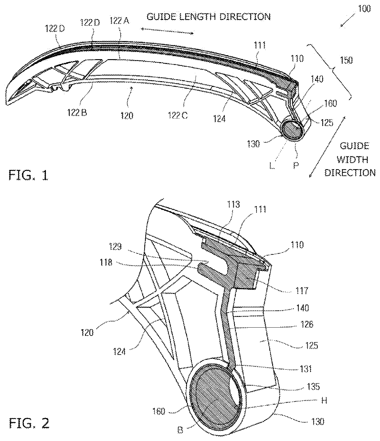
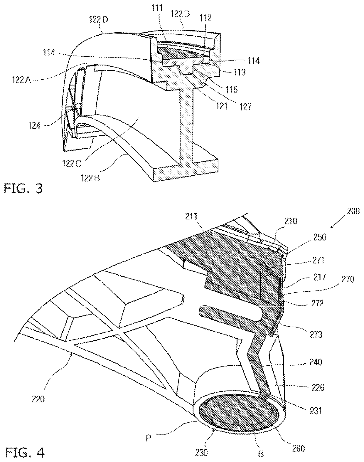
[0028]A tensioner lever 100 according to a first embodiment of the present invention will be described with reference to FIG. 1 to FIG. 3.

[0029]The tensioner lever 100 is a movable tensioner lever that guides a traveling drive chain while applying tension to the drive chain in corporation with a tensioner. The tensioner lever includes a synthetic resin shoe 110 having a traveling surface 111 on which the drive chain slides during travel along a guide length direction, a lever body 120 that supports the back side 112 of the shoe 110 along the guide length direction, and a pivotal support boss 130 provided at a proximal end in the guide length direction of the lever body 120 to allow the distal end thereof to swing. The shoe 110 and the lever body 120 are integrally formed and assembled together by double injection molding.

[0030]The guide length direction herein refers to a direction of the tensioner lever 100 along which the drive chain travels. The guide width direction refers to a ...

embodiment 2

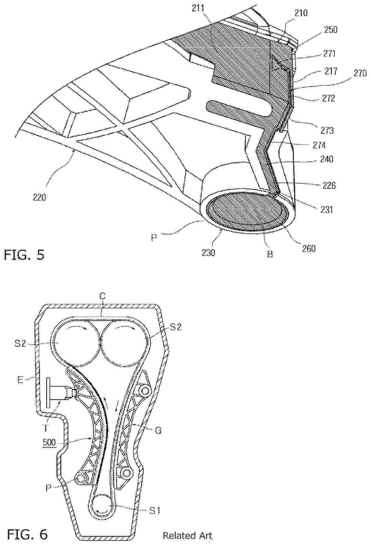
[0047]A tensioner lever 200 according to a second embodiment of the present invention has the same structure as that of the tensioner lever 100 according to the first embodiment except that, as shown in FIG. 4, an oil guide groove 270 is provided such as to extend from the traveling surface of the shoe 210 to the slide bearing member 260 that covers the inner circumferential surface of the pivotal support boss 230, as compared to the tensioner lever 100 according to the first embodiment. In FIG. 4, basically, the same reference numerals as those of the tensioner lever 100 according to the first embodiment, are given in the 200s to the components identical or corresponding to those of the tensioner lever 100 according to the first embodiment.

[0048]More specifically, the oil guide groove 270 includes an oil collecting part 271 that is a funnel-shaped recess provided on the traveling surface 211 at the proximal end of the shoe 210 and tapered outward in the guide length direction, a ch...


PUM


Abstract

The problem to be solved is to provide a tensioner lever that inhibits friction-induced wear or seizure on a surface of a pivoting support boss contacting a shoulder bolt so that high durability is achieved, and that is easily producible and enables cost reduction. As a solution to the problem noted above, the tensioner lever includes a shoe having a traveling surface, a lever body, and a pivotal support boss provided at a proximal end of the lever body to allow a distal end thereof to swing. The shoe and the lever body are integrally formed and assembled together by double injection molding. The lever body includes a slide bearing member, and a connecting part that connects the slide bearing member and the shoe. The slide bearing member, the connecting part, and the shoe are made of the same synthetic resin, and configured as a continuous one-piece component.

Description

BACKGROUND OF THE INVENTION1. Field of the Invention[0001]The present invention relates to a tensioner lever including a resin shoe having a traveling surface on which a drive chain slides during travel along a guide length direction, a lever body that supports the back side of the shoe along the guide length direction, and a pivotal support boss provided at a proximal end in the guide length direction of the lever body to allow a distal end thereof to swing, the shoe and the lever body being integrally formed and assembled together by double injection molding.2. Description of the Related Art[0002]In transmissions of car engines and the like are commonly used a timing system, wherein an endless drive chain such as a roller chain is passed over respective sprockets of a crank shaft and cam shafts inside the engine room and slidably guided by a guide shoe.[0003]In such an engine timing system, for example, as shown in FIG. 6, an endless drive chain C passes over a drive sprocket S1 m...

Claims


Application Information

Patent Timeline
Patent Type & Authority Applications(United States)
IPC IPC(8): F16H7/08F16H7/18
CPCF16H2007/185F16H7/08F16H2007/0872F16H7/18F16H57/042F16H57/0471F16H57/05
Inventor HASHIMOTO, HIROSHIKUREMATSU, YUJIMORI, KAORI
Owner TSUBAKIMOTO CHAIN CO
Why Eureka
Try Eureka