Adhesive dispensing device having optimized reservoir and capacitive level sensor

a technology of capacitive level sensor and reservoir, which is applied in the direction of liquid transfer device, liquid/fluent solid measurement, instruments, etc., can solve the problems of large amount of hot-melt adhesive held, low demand for molten adhesive, and most conventional adhesive dispensing device that does not operate continuously, etc., to reduce the velocity of air flow, reduce the retention volume of adhesive, and accelerate the delivery of additional adhesive

Active Publication Date: 2016-04-05
NORDSON CORP
View PDF69 Cites 5 Cited by
  • Summary
  • Abstract
  • Description
  • Claims
  • Application Information

AI Technical Summary

Benefits of technology

[0009]In one aspect, the plate element is a printed circuit board. In another aspect, the plate element is sized to engage a majority of the sidewall such that heat energy conducted through the sidewall is transferred to the plate element. This heat energy rapidly melts off any adhesive residue on the plate element above the fill level of the adhesive. Consequently, localized effects such as adhesive pellets sticking onto the plate element have minimal effect on the readings of fill level, unlike probe-like level sensors that may be affected for long periods of time by the sticking of adhesive pellets to the level sensor. Therefore, the plate element may be mounted flush with the sidewall. Additionally, a gasket may be located between the sidewall and the plate element to prevent adhesive from flowing between the sidewall and the plate element.
[0012]The fluid level sensor measurements of dielectric capacitance are also affected by the temperature of the level sensor, which varies as a result of cold pressurized air and unmelted adhesive periodicially entering the receiving space. In order to compensate for this, the fluid level sensor may also include a timer operatively coupled to the plate element and to a controller, and a control subroutine loaded onto the controller. The controller operates to receive the dielectric capacitance measurements and uses those measurements to control when a fill system is actuated to provide more unmelted adhesive to the receiving space. The control subroutine automatically compensates for temperature changes at the level sensor by estimating the temperature changes at the plate element based on a time measured by the timer since a most recent actuation of the fill system. As a result, the additional expense and maintenance associated with adding another temperature sensor at the level sensor is avoided.
[0016]In still another embodiment according to the invention, an adhesive dispensing device is configured to receive unmelted adhesive, melt and heat the adhesive, and then deliver the melted adhesive for dispensing. To this end, the adhesive dispensing device includes a heater unit adapted to heat and melt an adhesive to an elevated application temperature, a receiving space defined at least partially by a sidewall and positioned to feed the adhesive through the heater unit, and a reservoir positioned to receive the adhesive from the heater unit. The receiving space and the reservoir define a collective storage volume that is minimized such that the adhesive is not held at the elevated application temperature long enough to degrade or char during periods of low adhesive flow. The adhesive dispensing device also includes a pump for directing the adhesive out of the reservoir, and a level sensor for measuring a fill level of the adhesive within the receiving space. The level sensor includes a plate element having an electrically driven electrode and a ground electrode operatively connected for measuring a dielectric capacitance of air and adhesive acting as a dielectric between the driven and ground electrodes. The ground electrode may be electrically connected to the sidewall such that the sidewall forms at least a portion of the ground electrode. The level sensor is coupled into adjacent relationship with the sidewall such that the dielectric capacitance measured by the plate element varies with the fill level of the adhesive. This measurement enables the rapid delivery of additional adhesive to the receiving space following removal of adhesive from the reservoir to avoid emptying the heater unit and the reservoir during periods of high adhesive flow.
[0017]In one aspect, the collective volume of the receiving space and the reservoir is less than two liters. However, the level sensor is responsive enough to changes in the fill level of adhesive to prevent the receiving space and the heater unit from becoming depleted during periods of high throughput despite the relatively small retained volume of adhesive in the adhesive dispensing device. The adhesive dispensing device may further include a cyclonic separator unit configured to receive pellets of adhesive material in an air flow and reduce the velocity of the air flow and the pellets of adhesive before deposit into the receiving space. The pellets of adhesive define a pellet shape that is optimized to enable reliable flow of small amounts of adhesive material to refill the receiving space in a controlled manner. The pellet shape is also optimized to enclose a minimal amount of air when the adhesive is stacked such that the level of adhesive within the receiving space is accurately detected by the level sensor.

Problems solved by technology

However, large hoppers and reservoirs result in a large amount of hot-melt adhesive being held at the elevated application temperature within the adhesive dispensing device.
This holding of the hot-melt adhesive at the elevated application temperature may keep the hot-melt adhesive at high temperature for only about 1 to 2 hours during maximum flow, but most conventional adhesive dispensing devices do not operate continuously at the maximum flow.
To this end, all adhesive dispensing devices operate with long periods of time where the production line is not in use and the demand for molten adhesive is zero, or lower than the maximum flow.
During these periods of operation, large amounts of hot-melt adhesive may be held at the elevated application temperature for long periods of time, which can lead to degradation and / or charring of the adhesive, negative effects on the bonding characteristics of the adhesive, clogging of the adhesive dispensing device, and / or additional system downtime.
This collection of adhesive material, if not rapidly removed, may adversely affect the accuracy of readings from the level sensor.
However, it has proven difficult to remove this collection of adhesive material from probe-like level sensors during operation.
Thus, in circumstances of high throughput through the adhesive dispensing device, a lag in accurate readings from the level sensor could lead to insufficient or excessive levels of adhesive material within the hopper.

Method used


Image

  • Adhesive dispensing device having optimized reservoir and capacitive level sensor
  • Adhesive dispensing device having optimized reservoir and capacitive level sensor
  • Adhesive dispensing device having optimized reservoir and capacitive level sensor

Examples


Embodiment Construction

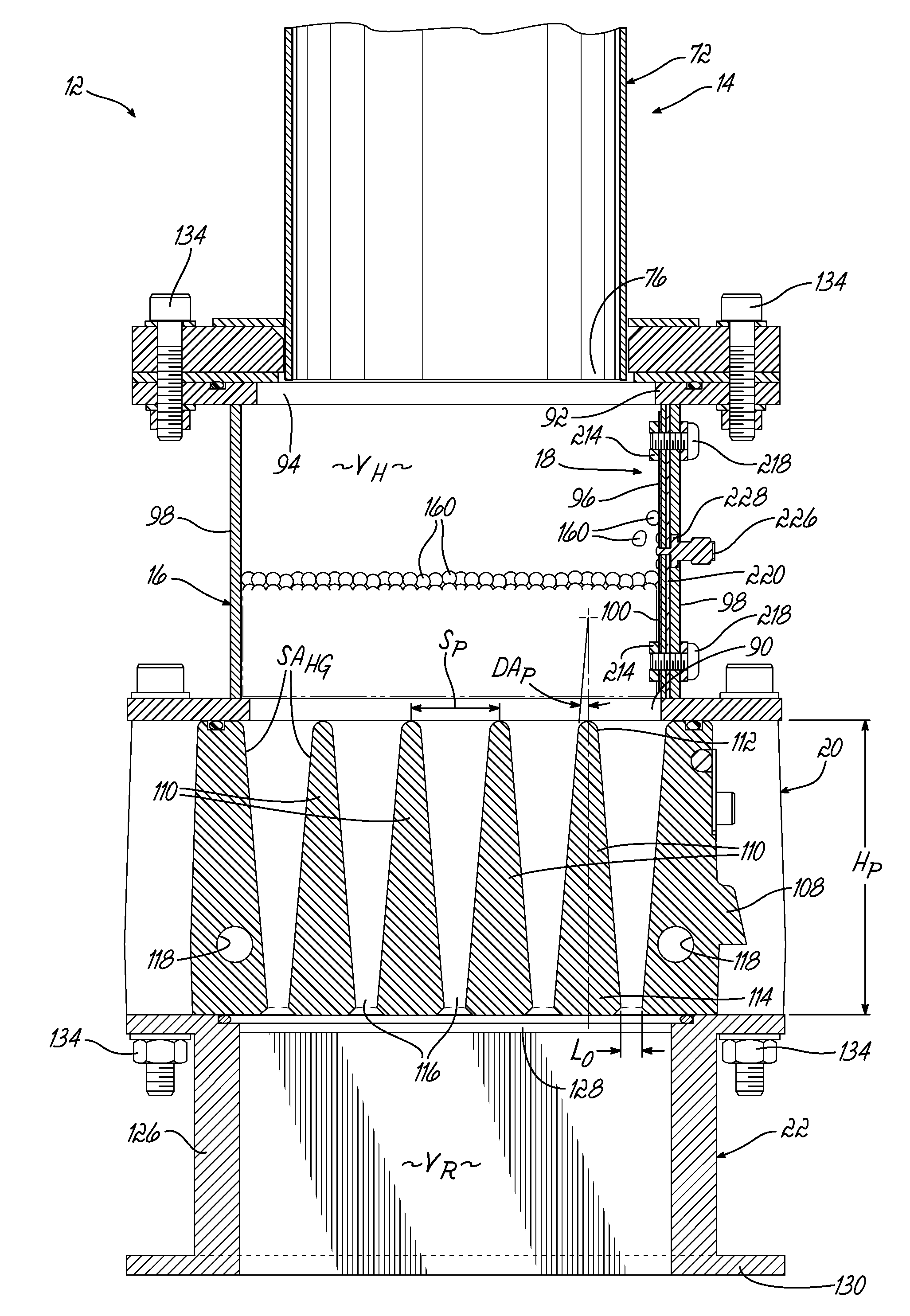
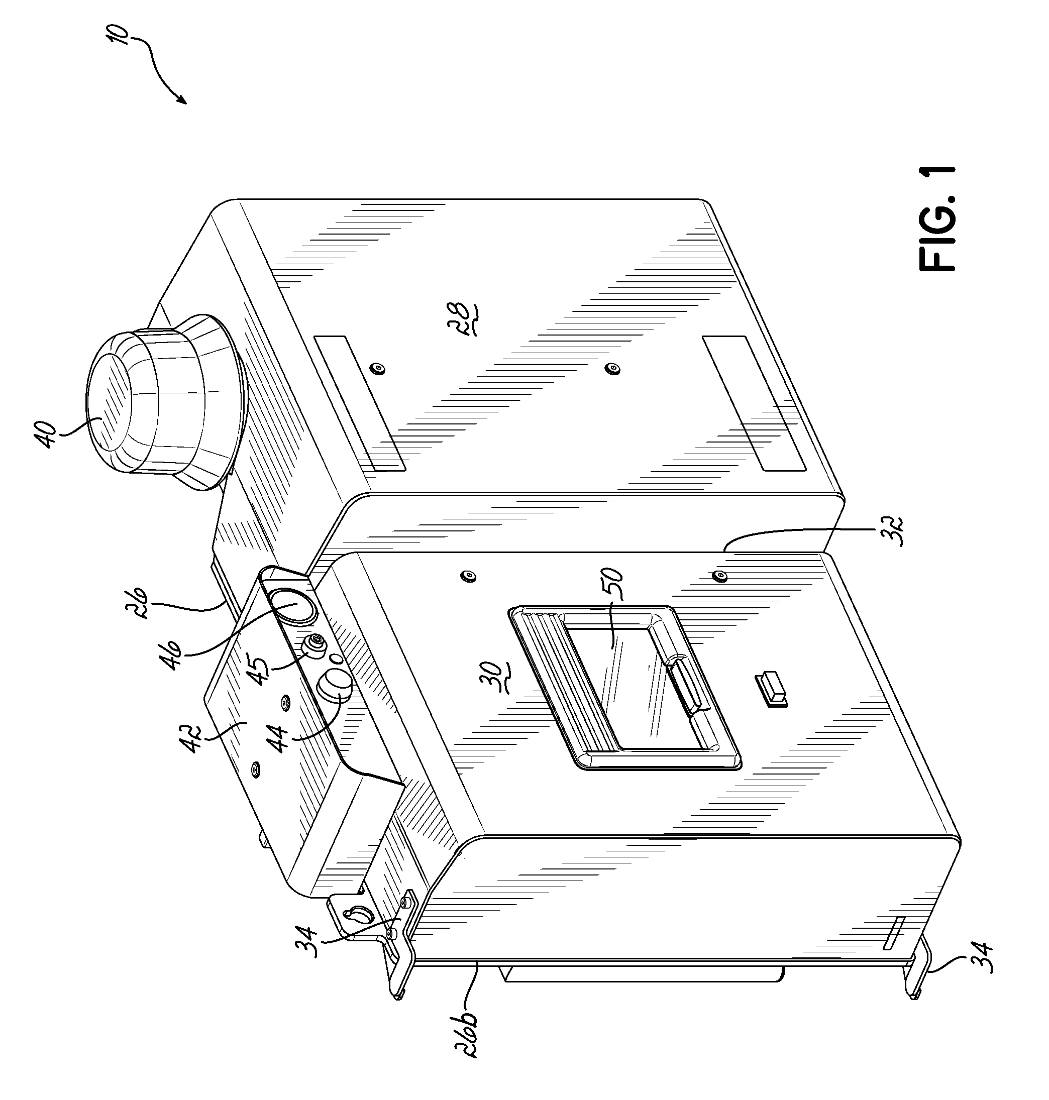
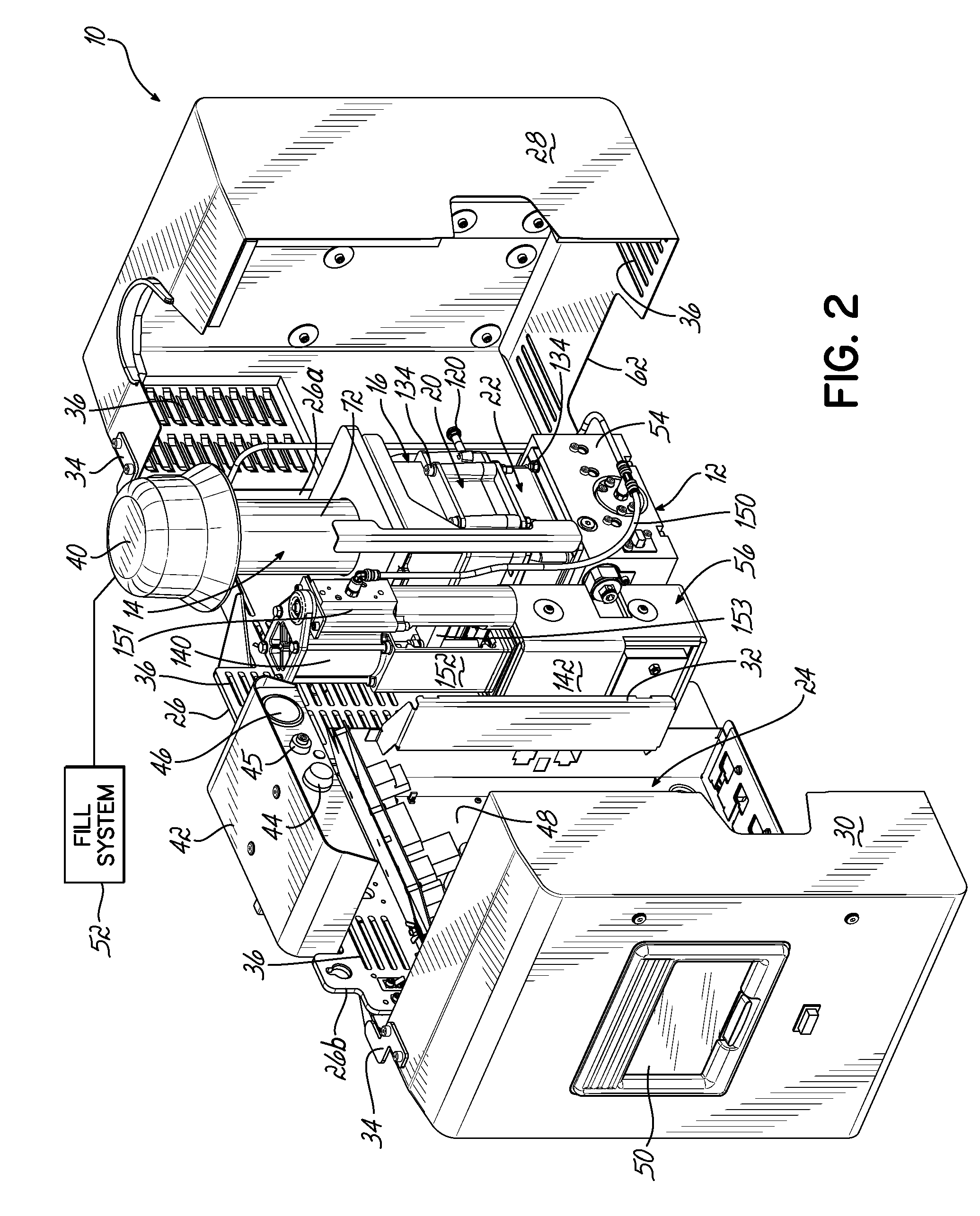
[0040]Referring to FIGS. 1 through 3, an adhesive dispensing device 10 in accordance with one embodiment of the invention is optimized to retain a significantly smaller amount of adhesive material at an elevated application temperature than conventional designs while providing the same maximum flow rate when necessary. More specifically, the adhesive dispensing device 10 includes a melt subassembly 12 that may include a cyclonic separator unit 14, a receiving space 16 with a level sensor 18, a heater unit 20, and a reservoir 22. Each of these elements is described in further detail below. The combination of these elements enables a maximum flow with approximately 80% less retained volume of molten adhesive material held at the elevated application temperature when compared to conventional designs.

[0041]The adhesive dispensing device 10 shown in FIGS. 1 through 3 is mounted along a wall surface, as described in U.S. patent application Ser. No. 13 / 659,291 to Jeter (entitled “Mountable...


PUM


Abstract

An adhesive dispensing device includes a heater unit for melting adhesive, a fill system communicating with a receiving space for feeding the heater unit, and a reservoir for receiving melted adhesive from the heater unit. The dispensing device also includes a capacitive level sensor located along a sidewall of the receiving space such that the level of adhesive in the receiving space can be detected by sensing the difference in dielectric capacitance where the adhesive is located compared to where air acts as the dielectric. The size of the driven electrode produces a broader sensing window capable of generating multiple control signals corresponding to different fill levels of adhesive. The receiving space and reservoir are minimized in size so that adhesive is not held at elevated temperatures long enough to char or degrade.

Description

CROSS-REFERENCE TO RELATED APPLICATION[0001]This application claims the benefit of U.S. Provisional Patent Application Ser. No. 61 / 703,454, filed on Sep. 20, 2012, the disclosure of which is incorporated by reference herein in its entirety.FIELD OF THE INVENTION[0002]The present invention generally relates to an adhesive dispenser, and more particularly, to components of a melt subassembly configured to heat adhesive prior to dispensing.BACKGROUND[0003]A conventional dispensing device for supplying heated adhesive (i.e., a hot-melt adhesive dispensing device) generally includes an inlet for receiving adhesive materials in solid or liquid form, a heater grid in communication with the inlet for heating the adhesive materials, an outlet in communication with the heater grid for receiving the heated adhesive from the heated grid, and a pump in communication with the heater grid and the outlet for driving and controlling the dispensation of the heated adhesive through the outlet. One or ...

Claims


Application Information

Patent Timeline
Patent Type & Authority Patents(United States)
IPC IPC(8): B67D7/22B05C11/10G01F23/26
CPCG01F23/263B05C11/1042G01F23/268A61B1/044G01F23/26
Inventor CLARK, JUSTIN A.CLARK, STEVENESTELLE, PETER W.OWEN, JEFFREY E.WOODLIEF, ROBERT J.JETER, DAVID R.
Owner NORDSON CORP
Why Eureka
Try Eureka