
Stop device for robot

a technology for stopping devices and robots, applied in the direction of programmed manipulators, mechanical devices, manufacturing tools, etc., can solve the problems of reducing the operating range, secondary damage, and longer stopping distance, and achieve the effect of improving the performance of servo motors

Inactive Publication Date: 2007-04-26
FANUC LTD
View PDF4 Cites 12 Cited by
  • Summary
  • Abstract
  • Description
  • Claims
  • Application Information

AI Technical Summary

Benefits of technology

[0012] In view of the above-described problem, it is an object of the present invention to provide a stop device for robot that is capable of stopping the motion of mutually movable parts of a robot in a short distance without increasing the size of a stopper member even if the mutually movable parts are moved at a higher speed due to an improved performance of a servo motor.
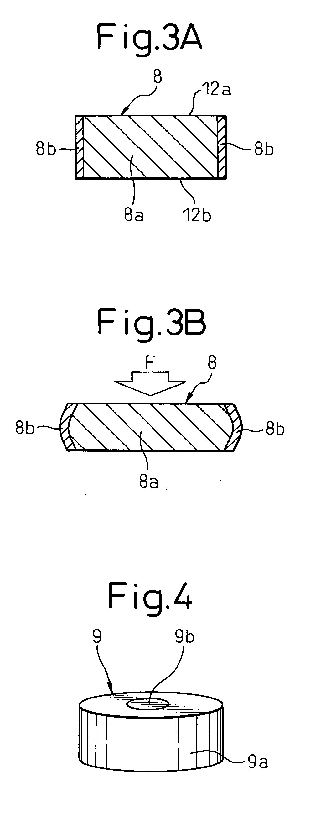
[0014] According to this invention, the stopper member is a combination member composed of at least two members of different hardness adhered to each other and combined such that opposite end faces of the member of highest hardness are adapted respectively to come into direct contact with the pair of mutually movable parts and to receive the compression load exerted between the pair of mutually movable parts at the time of collision in generally perpendicular direction to the opposite end faces, so that, when the stopper member is sandwiched between the pair of mutually movable parts due to the collision of the pair of mutually movable parts, the member of highest hardness receives the compression load F and produces high repulsive force. If the member of higher hardness deforms due to buckling, the repulsive force of the member of highest hardness is decreased. But, as the pair of mutually movable parts approach to each other, deformation of the member of lowest hardness due to compression proceeds, and repulsive force of the member of lowest hardness as the elastic restoring force is increased to stop the relative motion of the pair of mutually movable parts. Thus, stopping distance of the mutually movable parts of the robot can be shortened by the complementary effect of the member of highest hardness and the member of lowest hardness constituting the stopper member without increasing the size of the stopper member sandwiched between the pair of mutually movable parts.
[0016] According to this invention, the motor controller for controlling the servo motor comprises shock detecting means for detecting magnitude of shock produced when the pair of mutually movable parts collides with the stopper member and the magnitude of shock produced in the initial stage of the collision can be detected in early stage. Therefore, it is possible that the motor controller can perform the process for stopping the servo motor at an early stage. In this manner, delay in the timing of stopping the servo motor can be prevented, and the mutually movable parts can be stopped in a short distance.

Problems solved by technology

Therefore, there is a problem that a delay is produced in the timing to stop the servo motor and the operating stroke goes beyond the limit by an amount δ, so that the stopping distance becomes longer.
In the case where the kinetic energy of the robot arm 3 is large, the robot arm 3 may be damaged and this may give rise to secondary damage.
There is a problem that the upsizing also entails reducing of the operating range S of the robot arm 3 which should be kept as wide as possible.
There is another problem that the shape of the robot arm 3 is deformed and become unbalanced due to the large stopper member.

Method used


Image

  • Stop device for robot
  • Stop device for robot
  • Stop device for robot

Examples


Embodiment Construction

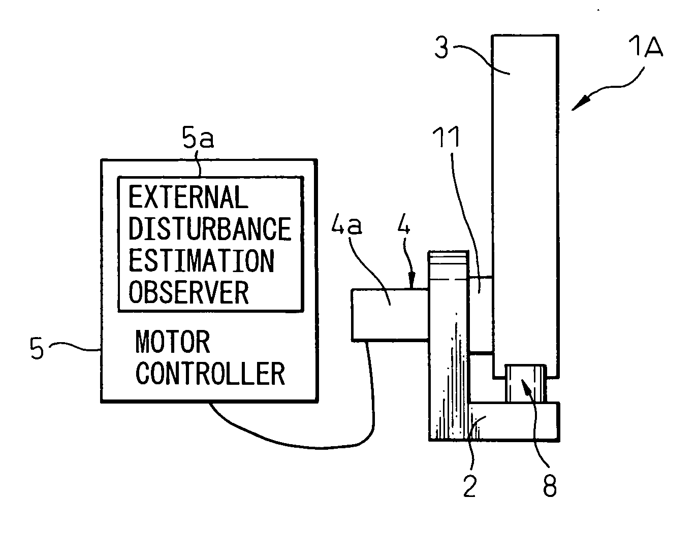
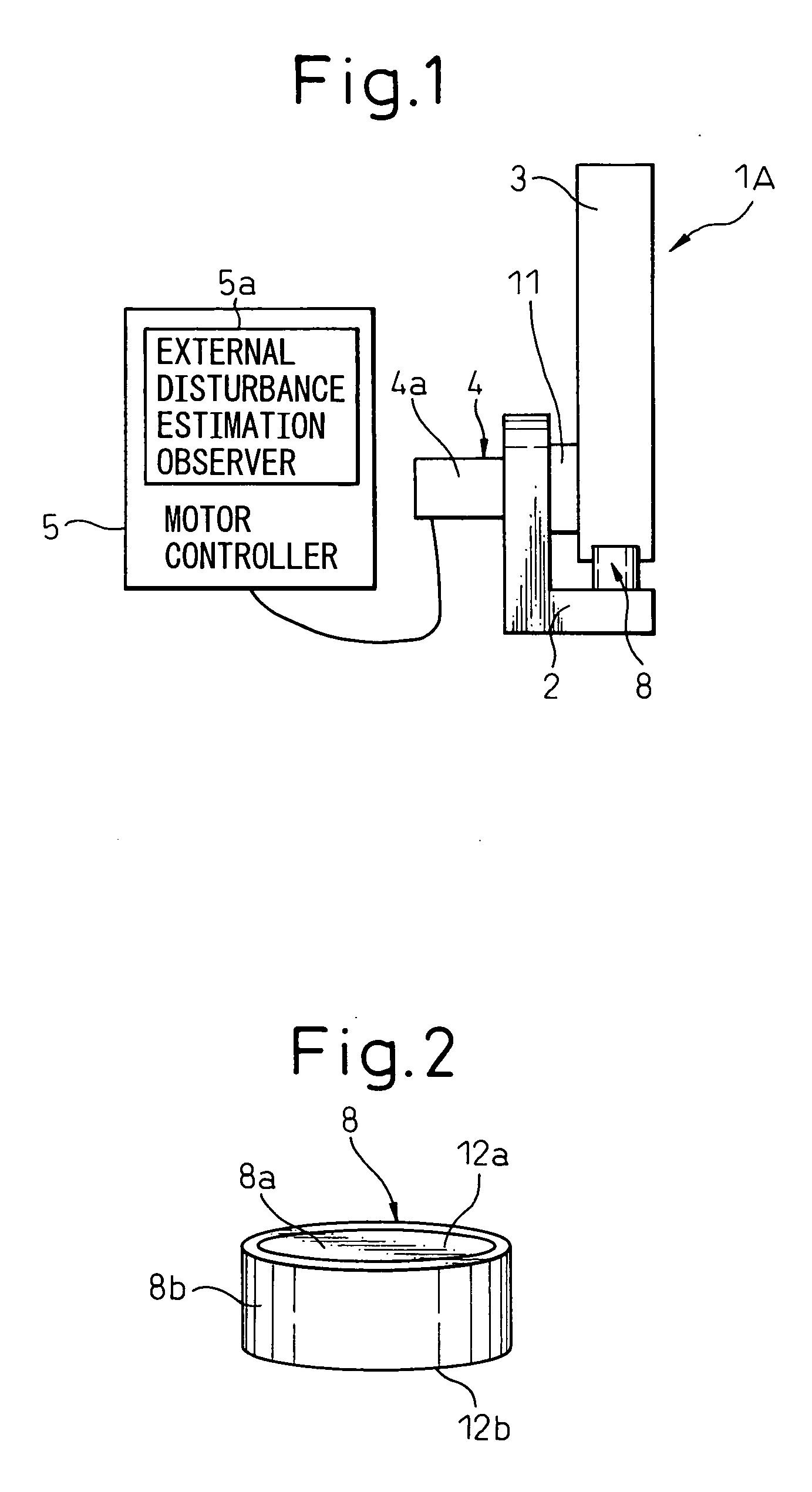
[0036] The present invention will be described in detail below with reference to appended drawings showing preferred embodiments of the stop device for a robot and the stopper member used in the device. FIG. 1 is a front view showing a stop device for a robot according to an embodiment of the present invention, and FIGS. 2, 3A and 3B are views showing a first embodiment of the stopper member used for the stop device for a robot as shown in FIG. 1. Constituents common to a conventional stop device for robot as shown in FIG. 8 are denoted by same reference numerals or symbols.

[0037] A stop device 1A for a robot of the present invention stops the motion of a robot arm 3 by collision with a counterpart member when the robot arm 3 moves beyond a predetermined operating range, and involves a base 2, a robot arm 3 rotatably mounted to the base 2, a servo motor 4 as a driving source for driving the robot arm 3, a motor controller 5 for controlling the speed and position of the servo motor ...


PUM

PropertyMeasurementUnit
hardnessaaaaaaaaaa
speedaaaaaaaaaa
repulsive forceaaaaaaaaaa

Abstract

A stop device for a robot for stopping the relative motion of a pair of mutually movable parts, having a stopper member provided at least one of the pair of mutually movable parts, the stopper member being sandwiched between the pair of mutually movable parts when the pair of mutually movable parts collide with the stopper member, wherein the stopper member is a combination member composed of at least two members of different hardness adhered to each other, such that opposite end faces of one member of highest hardness of at least two members, are adapted respectively to come into direct contact with the pair of mutually movable parts and to receive a compression load exerted between the pair of mutually movable parts at a time of collision in a generally perpendicular direction to the end faces.

Description

RELATED APPLICATION [0001] The present application is based on, and claims priority from, Japanese Application Number 2005-311547, filed Oct. 26, 2005, the disclosure of which is hereby incorporated, by reference, in its entirety. BACKGROUND OF THE INVENTION [0002] 1. Field of the Invention [0003] The present invention relates to a stop device for a robot provided on at least one of a pair of mutually movable parts, moved relatively to each other, having a stopper to be sandwiched between the mutually movable parts to stop the relative motion when the mutually movable parts collide with each other. [0004] 2. Description of the Related Art [0005] An example of stop device for a robot for stopping relative motion of a pair of mutually movable parts is shown in FIG. 8. The relative motion of a movable part is stopped relative to a fixed part. In FIG. 8, one of a pair of mutually movable parts is a base 2 as a fixed part, and the other of the pair of mutually movable parts is a robot ar...

Claims


Application Information

Patent Timeline
Patent Type & Authority Applications(United States)
IPC IPC(8): F16D71/00B23Q17/00
CPCB25J9/101B25J13/085B25J19/0091Y10T29/49764F16F3/093F16F2230/007F16F1/371
Inventor KINOSHITA, SATOSHITAKIKAWA, RYUJI
Owner FANUC LTD
Learn More