
Light amount control device for endoscope

a technology of light amount control and endoscope, which is applied in the field of endoscope, can solve the problems of inability to adjust the amount of illuminating light entering the light guide to be suitable according to the diameter of the light guide, and excessive amount of emitted light from the end of the scop

Inactive Publication Date: 2007-04-26
ASAHI KOGAKU KOGYO KK
View PDF11 Cites 13 Cited by
  • Summary
  • Abstract
  • Description
  • Claims
  • Application Information

AI Technical Summary

Benefits of technology

[0007] Therefore, an objective of the present invention is to provide an endoscope where the amount of illuminating light can be controlled according to a light guide used, and where the structure thereof is simple.
[0009] The first light amount control device may further include a determination processor that determines whether the amount of the illuminating light should be lowered or not, based on the scope identification information. The light amount controller may lower the amount of the illuminating light when the determination processor determines that the amount of the illuminating light should be lowered.

Problems solved by technology

The reason for such a cut mask is that when a scope including a light guide with a wide diameter is used, the amount of illuminating light emitted from the end of the scope may be excessive.
If a cut mask for reducing the amount of illuminating light entering a light guide is provided, the structure of the endoscope becomes complicated.
Further, in such a case, because the diameter of the cut mask is not adjustable, adjusting the amount of illuminating light entering a light guide to be suitable according to the diameter of the light guide is impossible.
In a case where a plurality of cut masks are provided, and one of them is selected for adjusting the amount of illuminating light entering a light guide, selecting a cut mask having a desirable diameter is not always possible; therefore, optimized adjustment may be impossible.
In addition, providing a plurality of cut masks necessitates a more complicated structure for the endoscope.

Method used


Image

  • Light amount control device for endoscope
  • Light amount control device for endoscope
  • Light amount control device for endoscope

Examples


Embodiment Construction

[0025] Hereinafter, the preferred embodiment of the present invention is described with reference to the attached drawings.

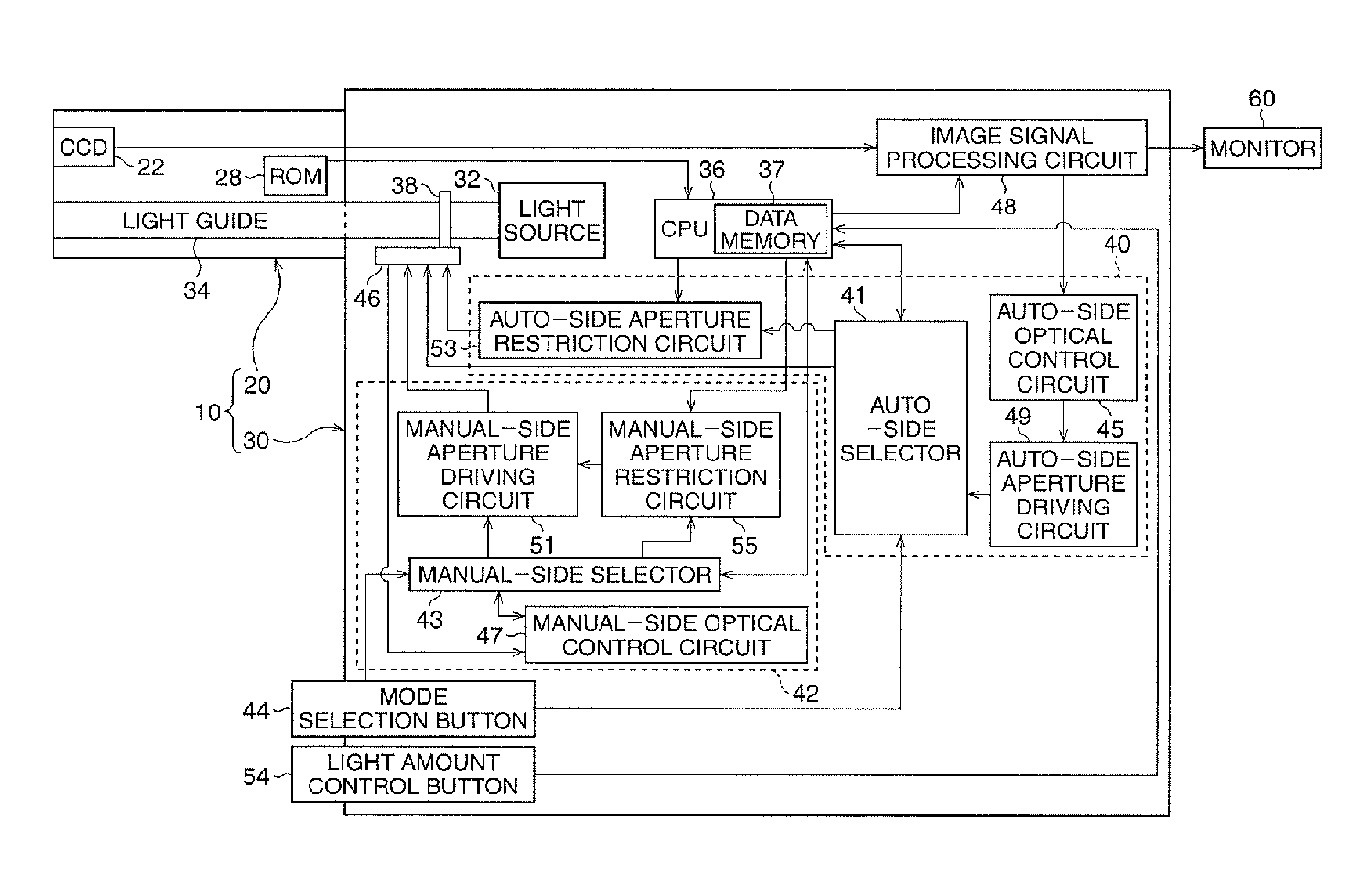
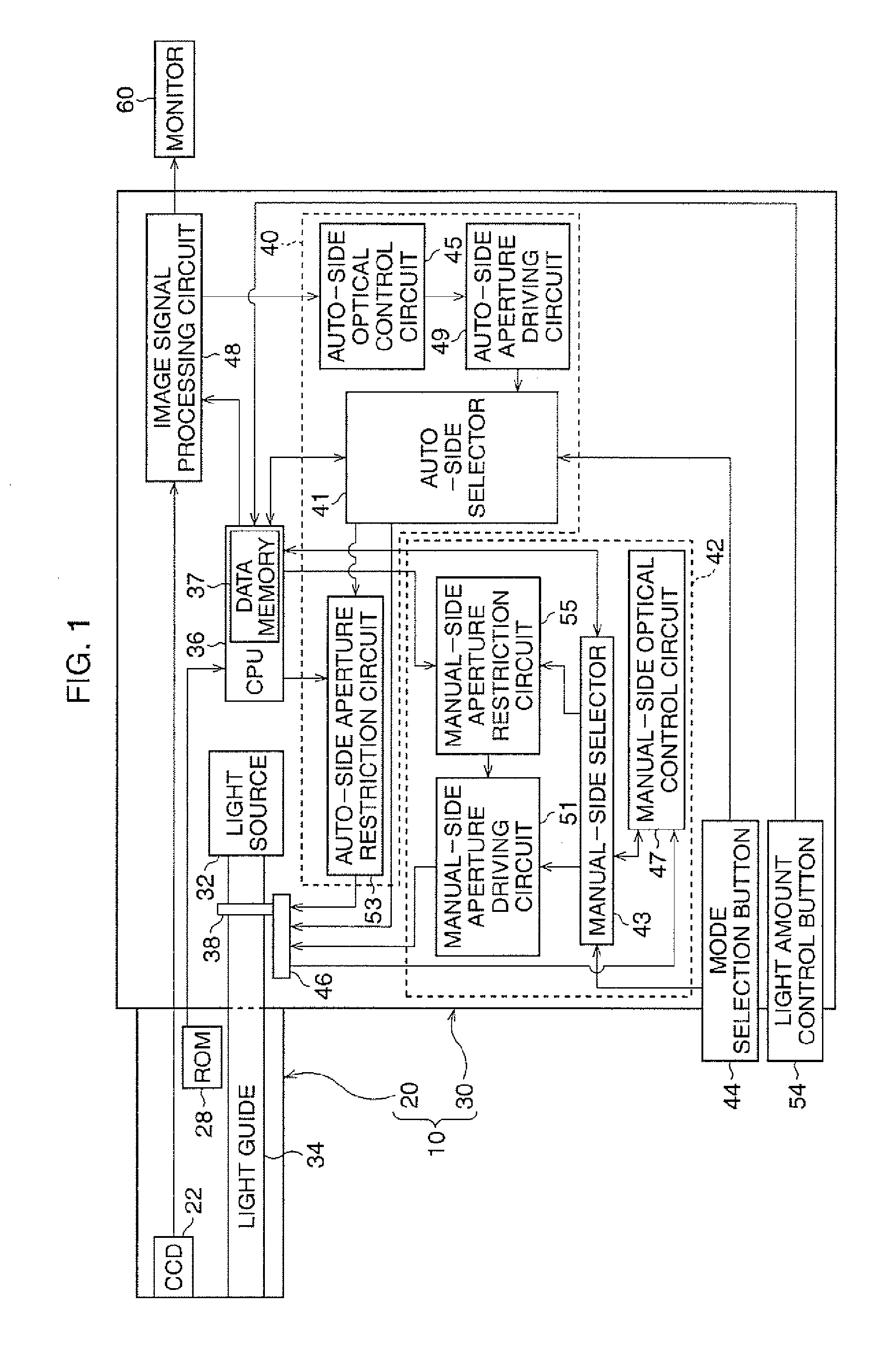
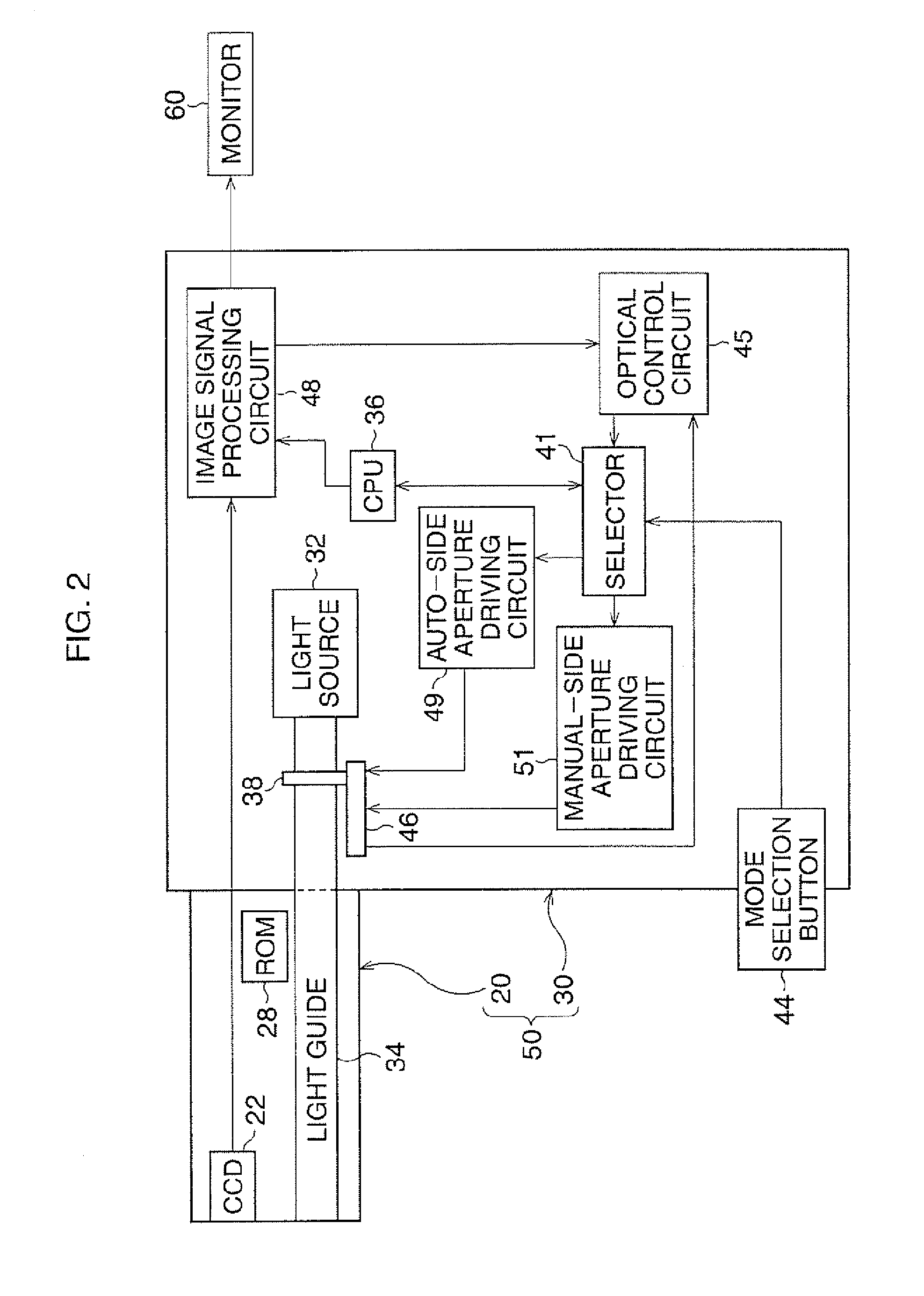
[0026] As shown in FIG. 1, an electronic endoscope 10 includes a scope 20 and a processor 30. The scope 20 is used for observing and photographing inside a body cavity of a subject person. The processor 30 provides illuminating light for the scope 20, and processes image signals transferred from the scope 20. The scope 20 is selectively and detachably connected to the processor 30. To the processor 30, a plurality of different scopes, including the scope 20, can be connected, and one of the scopes selected by a user is connected to the processor 30 and used. Further, a monitor 60 is connected to the processor 30.

[0027] In the processor 30, a CPU 36 for controlling the entirety of the processor 30, and a lighting unit 32, which emits illuminating light for illuminating a subject, are provided. When electronic power is supplied under the control of the CPU 36, t...


PUM


Abstract

A light amount control device is provided in an endoscope processor. To the endoscope processor, a plurality of scopes that each has a light guide to transmit illuminating light can be selectively and detachably connected. The light amount control device includes a light source and a light amount controller. The light source emits the illuminating light. The light amount controller controls the amount of the illuminating light entering the light guide. The light amount controller controls the amount of the illuminating light, according to the light transmission characteristics of the light guide in the scope, based on scope identification information for identifying the scope that is connected to the endoscope processor.

Description

BACKGROUND OF THE INVENTION [0001] 1. Field of the Invention [0002] The present invention relates to an endoscope that can control the amount of light. [0003] 2. Description of the Related Art [0004] An endoscope device generally has a processor including a light source for illuminating a body cavity to be observed and other components, and a processor that has a light guide for transmission of illuminating light from the light source and other components, and is detachably connected to the processor. The illuminating light from the light source is transmitted by the light guide, and is emitted from the end of the scope to a subject. [0005] Usually, a plurality of scopes, where various kinds of light guides having different quantities or diameters of fibers are provided, are connected to a processor and are used. An endoscope where a cut mask is provided at the light-entering end of a light guide, to control the generation of heat at the end of the scope, is known. The reason for su...

Claims


Application Information

Patent Timeline
IPC IPC(8): G01J1/32A61B1/00
CPCG02B23/2469A61B1/0669A61B1/0655
Inventor KOBAYASHI, SHOTARO
Owner ASAHI KOGAKU KOGYO KK
Learn More