Shifted transmission mock for nuclear medical imaging

a nuclear medical imaging and transmission mock technology, applied in the field of nuclear medical imaging, can solve the problems of unfavorable implementation, unable to meet the requirements of real mock scans,

Inactive Publication Date: 2007-04-26
SIEMENS MEDICAL SOLUTIONS USA INC
View PDF3 Cites 18 Cited by
  • Summary
  • Abstract
  • Description
  • Claims
  • Application Information

AI Technical Summary

Benefits of technology

[0013] Ideally, estimation of the emission contamination of a transmission scan is based on a real mock scan (i.e. an additional transmission scan without the source being exposed). Such a real mock scan, however, may be clinically unpractical since it may require additional scan time of about five minutes or more. Another possible method, the estimation of emission contamination based on phantoms after uniform or non-uniform scaling, is also undesirable for implementation at the clinical level. What is desired is a method of estimation of emission contamination that does not involve additional scan time for acquisition of list-mode data and that is sufficiently robust and general to be implemented at clinical level.

Problems solved by technology

Such a real mock scan, however, may be clinically unpractical since it may require additional scan time of about five minutes or more.
Another possible method, the estimation of emission contamination based on phantoms after uniform or non-uniform scaling, is also undesirable for implementation at the clinical level.

Method used


Image

  • Shifted transmission mock for nuclear medical imaging
  • Shifted transmission mock for nuclear medical imaging
  • Shifted transmission mock for nuclear medical imaging

Examples


Embodiment Construction

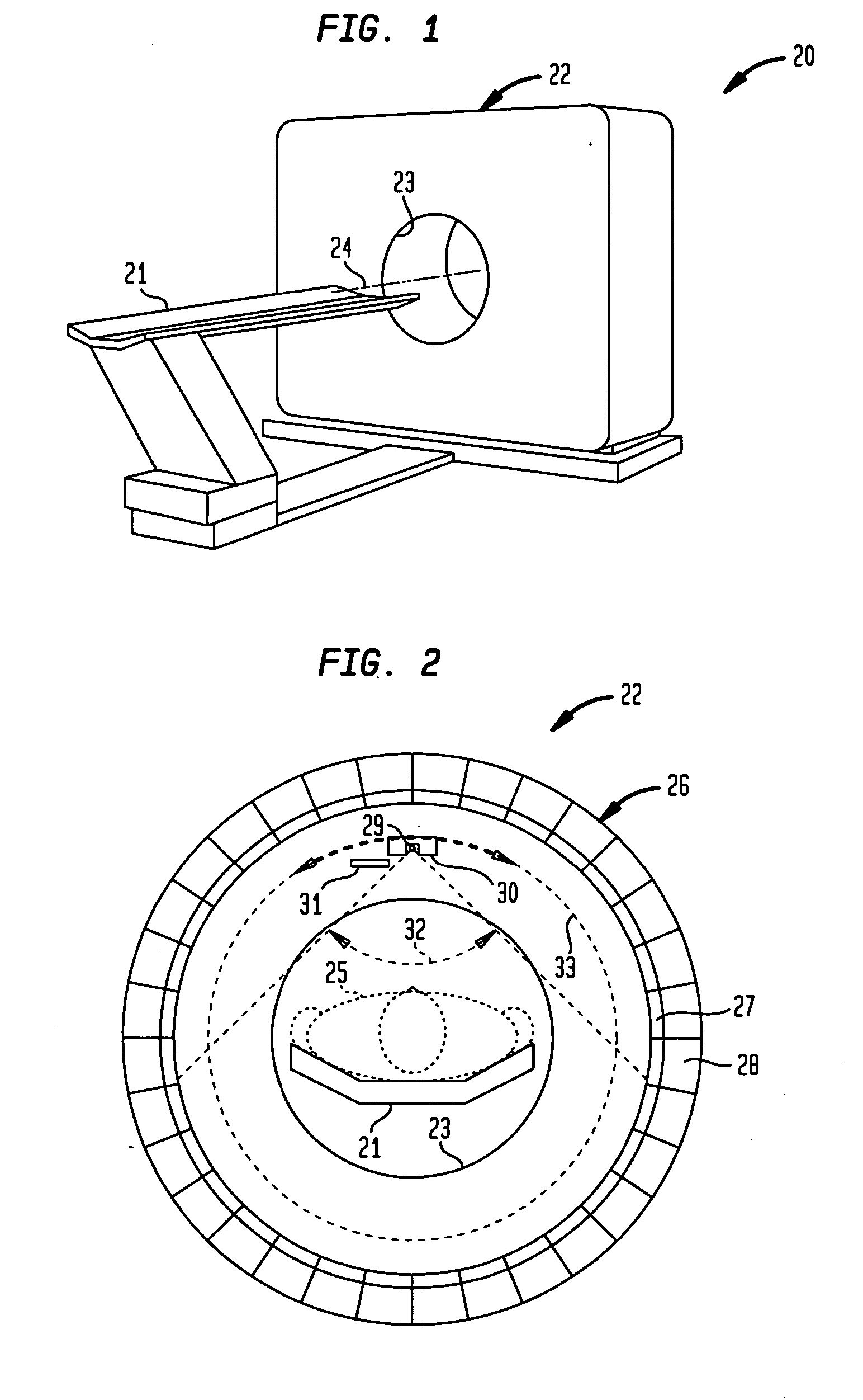
[0034] With reference to FIG. 1, there is shown one example of a positron emission tomographic (PET) imaging apparatus generally designated 20, to which the invention is applicable. The apparatus 20 includes a bed 21 for supporting a human patient (25 in FIG. 2) and a detector assembly 22 having a cylindrical hole 23 for receiving the patient. The bed 21 is aligned along an axis 24 of the hole 23 and is translated relative to the detector assembly along this axial direction for scanning of the whole body of the patient.

[0035] As further shown in FIG. 2, when the patient 25 is received in the hole 23, the patient is surrounded by a gamma detector array 26 including scintillating crystals 27 and photo-detectors 28. The scintillating crystals, for example, may be made of Lutetium oxyorthosilicate (LSO) and are arranged in a cylindrical array having a spacing of about 4 mm between the centers of adjacent crystals in the axial and trans-axial directions. The photo-detectors, for example...


PUM

PropertyMeasurementUnit
angleaaaaaaaaaa
energyaaaaaaaaaa
diameteraaaaaaaaaa

Abstract

Emission contamination data are collected in a shifted mock scan simultaneous with the collection of transmission data during a transmission scan of a patient with a collimated gamma point source, the transmission data are corrected with the emission contamination data, and the corrected transmission data are used for attenuation correction of emission data for reconstruction of an emission image of the patient. In a preferred implementation, when the point source is at a particular axial location and illuminates an axial beamwidth of “Fz” over the gamma detector, emission contamination data are collected from the gamma detector over an axial separated region “Fz′” having about the same axial extent but axially displaced by about half of the axial field of view (FOV).

Description

BACKGROUND OF THE INVENTION [0001] 1. Field of the Invention [0002] The present invention relates generally to nuclear medical (NM) imaging such as such as positron emission tomography (PET) and single photon emission computed tomography (SPECT), and more particularly to correction of emission contamination in transmission scans. [0003] 2. Description of the Background Art [0004] Medical imaging is one of the most useful diagnostic tools available in modern medicine. Medical imaging allows medical personnel to non-intrusively look into a living body in order to detect and assess many types of injuries, diseases, conditions, etc. Medical imaging allows doctors and technicians to more easily and correctly make a diagnosis, decide on a treatment, prescribe medication, perform surgery or other treatments, etc. [0005] There are medical imaging processes of many types and for many different purposes, situations, or uses. They commonly share the ability to create an image of a bodily regio...

Claims


Application Information

Patent Timeline
Patent Type & Authority Applications(United States)
IPC IPC(8): G01N23/04G01T1/24
CPCG01T1/1615
Inventor SIBOMANA, MERENCELENOX, MARK W.BYARS, LARRYMICHEL, CHRISTIAN J.NEWPORT, DANNY
Owner SIEMENS MEDICAL SOLUTIONS USA INC
Why Eureka
Try Eureka