Dynamic hermetic barrier for use with implantable infusion pumps

a technology of infusion pump and hermetic barrier, which is applied in the direction of valves, mechanical devices, engine components, etc., can solve the problems of shortening the expected useful operative life of the device, adversely and affecting the operation of the device. , to achieve the effect of reducing stress to a braze lin

Inactive Publication Date: 2007-04-26
CODMAN & SHURTLEFF INC
View PDF17 Cites 26 Cited by
  • Summary
  • Abstract
  • Description
  • Claims
  • Application Information

AI Technical Summary

Benefits of technology

[0017] According to yet another embodiment, a membrane includes a curved peripheral edge that is sized and shaped to snuggly seat within the peripheral brazing groove located within a membrane support disc. This arrangement helps minimize stress to a braze (or weld) line due to membrane flexure.

Problems solved by technology

In some situations, the “outside environment” (environment located outside the barrier) is hazardous and includes elements or conditions that will adversely affect the operation of the device or shorten its expected useful operative life.
However, should the device require cross-barrier mechanical interaction, such as linear, angular, or rotational displacement, then the barrier must accommodate the mechanical displacement and the corresponding mechanical stress and fatigue that will likely occur.
Unfortunately, such rubber and plastic structures, albeit tough and resistant, fail in extreme environmental conditions, including environments having any of a variety of chemicals, radiation, positive and negative pressures, mechanical abrasion, sunlight, and high temperatures (above 300 degrees F.) and those below freezing.
One such harsh environment is that of an autoclave, wherein steam is used to sterilize devices intended to be used within or in connection with a human patient.
The super-heated water can easily destroy or severely damage such soft flexible non-metallic materials, even before they reach their intended operative environment.
The flat metal disc has proved quite useful and effective for many devices and situations, but, in some cases may be limited in operative cycles before succumbing to the persistent mechanically-generated stress and fatigue.

Method used


Image

  • Dynamic hermetic barrier for use with implantable infusion pumps
  • Dynamic hermetic barrier for use with implantable infusion pumps
  • Dynamic hermetic barrier for use with implantable infusion pumps

Examples


first embodiment

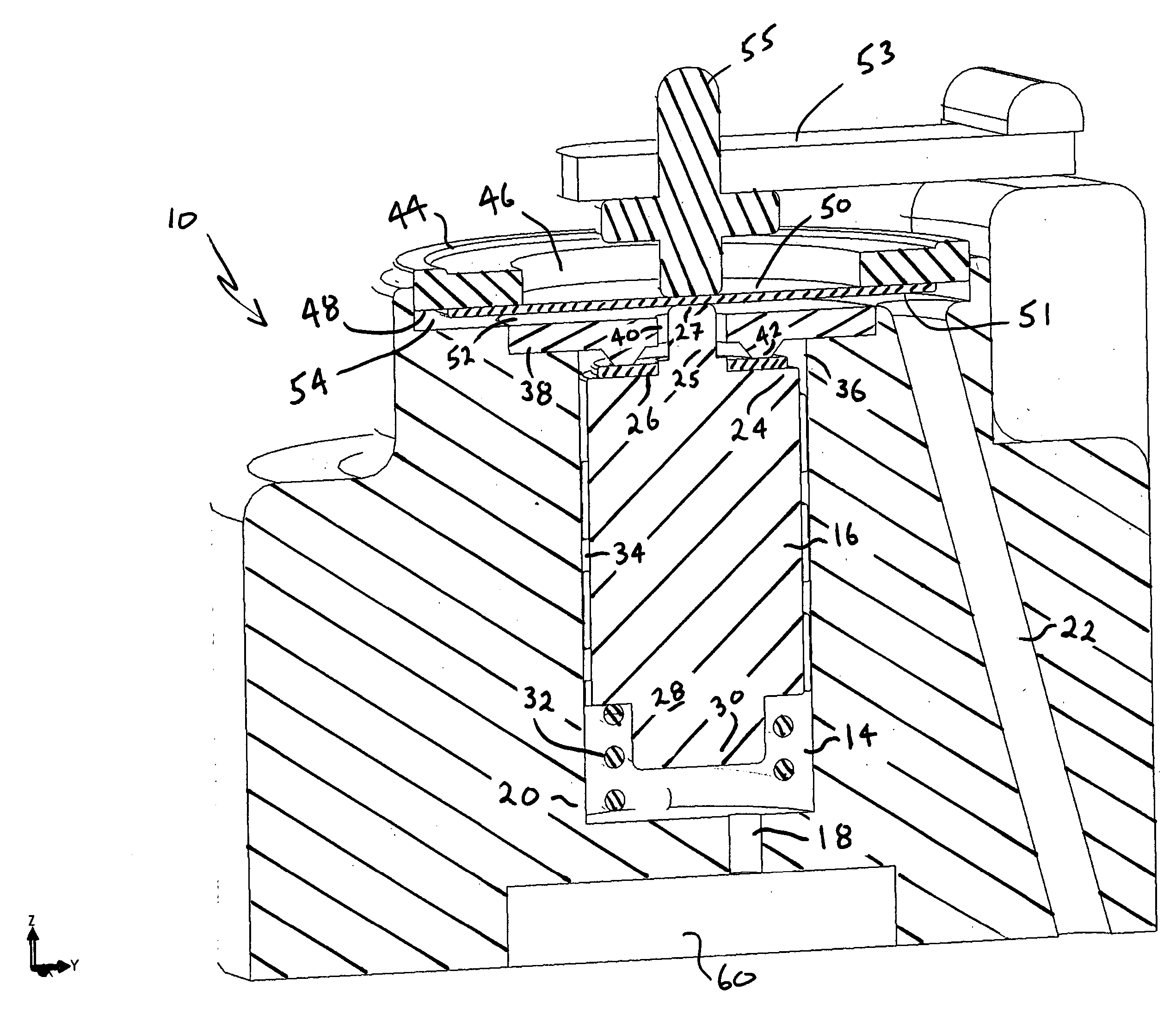
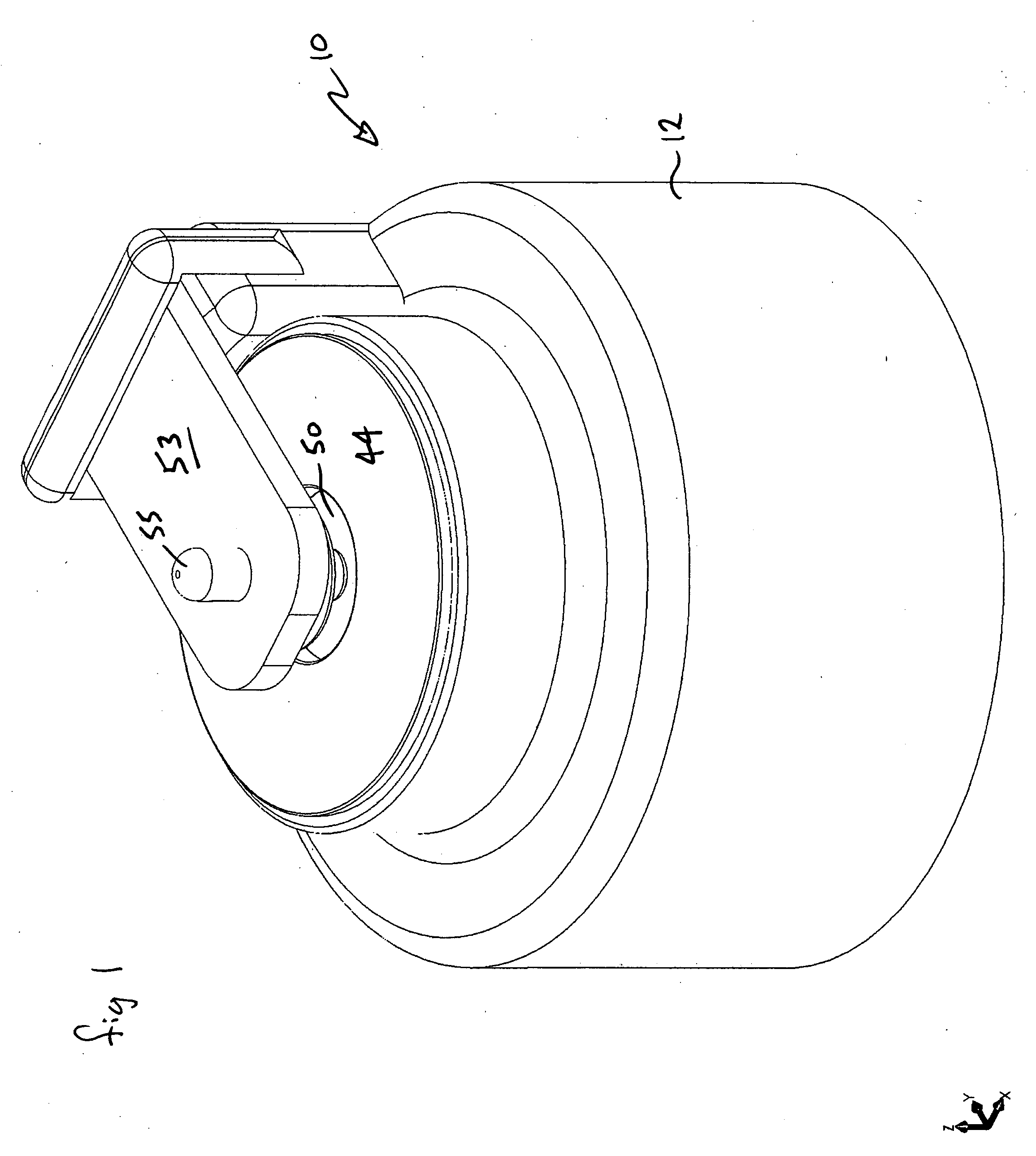
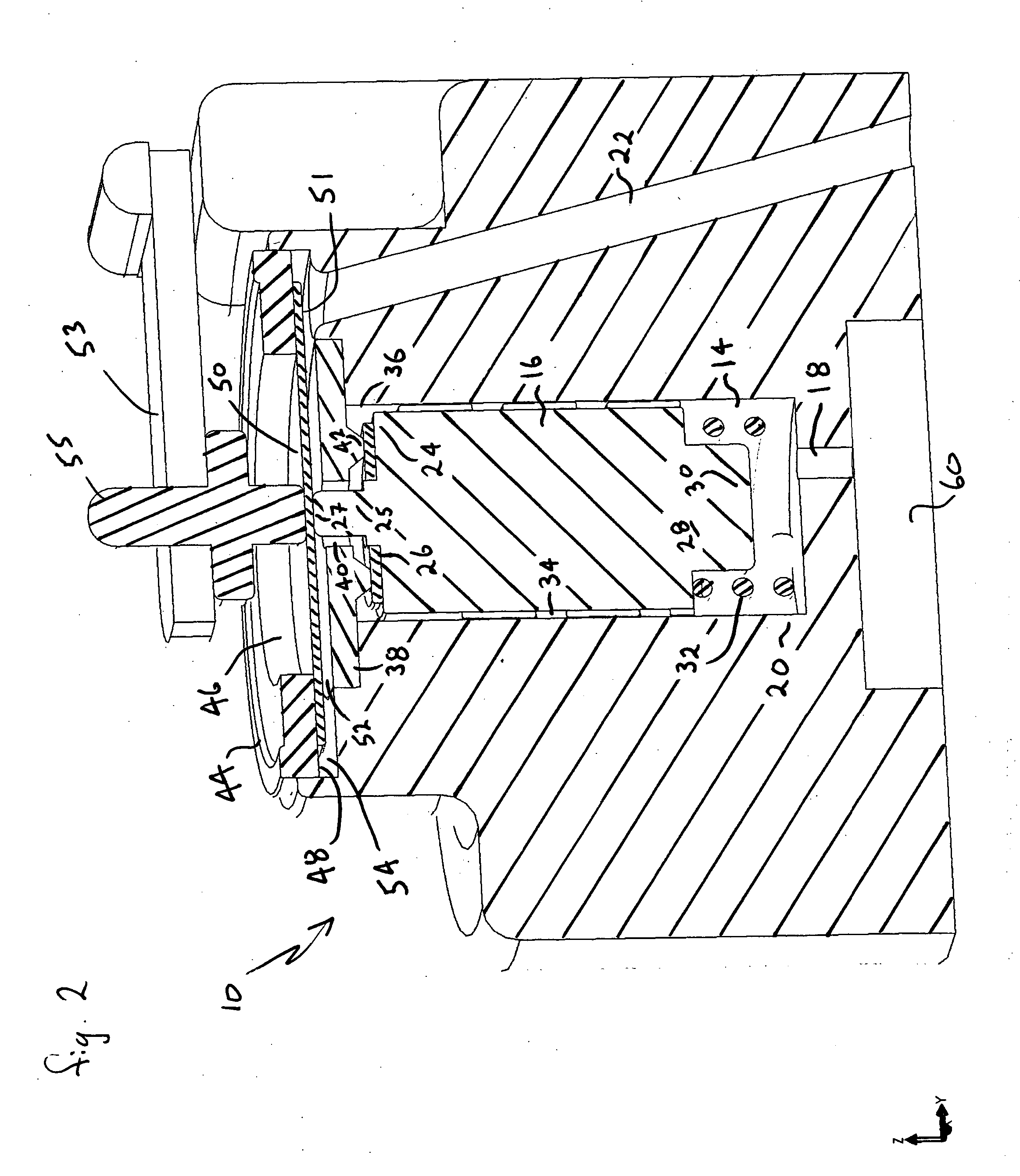
[0052] Referring to FIGS. 4, 5, 6, and 7, a valve assembly 100 (for clarity, shown without a body structure 12) is shown including all the same parts as the valve assembly 10, shown in FIGS. 1, and 2 and described above, except that the flat, coin-like membrane 50 has been replaced with a membrane 102 which includes at least one integrally formed concentric ripple 104, according to the invention. Assuming a metal membrane, each ripple 104 is preferably stamped using an appropriate die. The stamping die (not shown) forms at least an upper portion 106 or a lower portion 108, but preferably a series of ripples 104 into membrane 102, as shown in FIGS. 4 through 7. Concentric ripples 104 define a central contact circle 110 against which actuator pin 55 and contact pin 25 will abut, on upper surface 112 and lower surface 114, respectively, of membrane 104.

[0053] In operation of valve assembly 100, as actuation pin 55 is linearly displaced downward against piston 16, by piezo crystal 53, m...

second embodiment

[0055] Referring now to FIGS. 8, 9, 10, 11, and 12, a valve assembly 200, (again, for clarity, shown without a body structure 12) is shown including all the same parts as the valve assembly 10, shown in FIGS. 1, and 2 and described above, except that the flat, coin-like membrane 50 has now been replaced with a membrane 202 which includes a bellows structure, according to the invention. As shown in FIGS. 9 and 12, a bellows membrane 202 includes at least one inward concentric bend 204 and at least one outward concentric bend 206, and further defines a contact circle 208 and a mounting flange 210. Mounting flange 210 is brazed (or welded) to a portal support ring 212 which preferably includes a circular recess 214 on an upper surface 216, as shown in FIGS. 10 and 12. To help maintain a relatively low-profile valve assembly 200, bellows membrane 202 is preferably mounted to upper surface 214 and portal support ring 212 preferably includes a central opening 215 that is sized and shaped ...

fourth embodiment

[0060] A portal membrane mounting ring 412 is shown having a central opening 414, a peripheral brazing groove 416 and a rounded support surface 418. According to the invention, membrane 400 is sized and shaped to snuggly fit into portal membrane mounting ring 412 so that upwardly curved peripheral edge 410 is positioned within brazing groove 416 and against rounded support surface 418. The purpose of this curved peripheral edge 410 and the brazing groove 416 is to discourage stress on the brazing weld caused by repeated flexing movement of the membrane 400. The curved peripheral edge 410 of this fourth embodiment can be applied to any shaped membrane described in this application, as well as the flat, coin-like membrane of the prior art.


PUM


Abstract

A valve mechanism for use in an implant able infusion pump includes a fluid compartment and a dry-component compartment. The compartments are sealed so that fluid cannot pass between compartments. A flexible membrane is located between the compartments and allows limited mechanical displacement between the compartments, yet prevents any fluid communication therebetween. The fluid compartment includes a valve that is positioned between the inlet chamber and the outlet chamber. The valve includes a movable trigger member that selectively causes the valve to move between an open position and a closed position. The trigger member is positioned adjacent to the first surface of the membrane. The dry-component compartment includes an actuator, which is positioned against the membrane so that generated movement of the actuator may selectively transfer to the trigger member through non-invasive deformation of the flexible membrane. In this arrangement, the valve located within the hermitically-sealed fluid compartment is effectively controlled from the dry component compartment. The flexible membrane includes at least one deformed region that extends beyond the membrane plane, which can be ripple-shaped or bellows-shaped.

Description

BACKGROUND OF THE INVENTION [0001] 1) Field of the Invention [0002] This invention generally relates to hermetically-sealed devices that have a sealed barrier (or membrane), and more particularly to such hermetically-sealed devices that include mechanical interaction across the barrier. [0003] 2) Discussion of Related Art [0004] A variety of mechanical and electromechanical devices must operate in environments that require the devices to be completely isolated within a protective barrier. In some situations, the “outside environment” (environment located outside the barrier) is hazardous and includes elements or conditions that will adversely affect the operation of the device or shorten its expected useful operative life. In such hazardous environments, the device must be completely sealed and the protective barrier must be made with the particular hazard in mind. For example, in a chemical-production facility, a temperature sensor may have an operative environment that includes a ...

Claims


Application Information

Patent Timeline
Patent Type & Authority Applications(United States)
IPC IPC(8): F16K31/00
CPCA61M5/16881A61M39/22F16K1/34F16K31/006
Inventor BORK, TORALF
Owner CODMAN & SHURTLEFF INC
Why Eureka
Try Eureka