Light-emitting diode assembly and method of fabrication

a technology of light-emitting diodes and assembly methods, which is applied in the direction of discharge tube main electrodes, semiconductor devices of light sources, lighting and heating apparatus, etc., can solve the problems of significant reduction of the lifespan of leds and the difficulty of efficiently dispersing heat generated by leds

Inactive Publication Date: 2007-04-26
HON HAI PRECISION IND CO LTD
View PDF7 Cites 142 Cited by
  • Summary
  • Abstract
  • Description
  • Claims
  • Application Information

AI Technical Summary

Benefits of technology

[0008] The present invention relates, in another aspect, to a method of packaging a light-emitting diode (LED). The method includes steps of: (A) providing a heat-absorbing member wherein a working fluid is provided in the heat-absorbing member; (B) attaching an LED die directly to the heat-absorbing member; and (C) thermally attaching a heat-dissipating member to the heat-absorbing member.

Problems solved by technology

If not rapidly and efficiently removed, the heat produced may significantly reduce the lifespan of the LED.
In order to increase the overall lighting brightness, a plurality of LEDs are often incorporated into a single lamp, in which case how to efficiently dissipate heat generated by these LEDs becomes a challenge.

Method used


Image

  • Light-emitting diode assembly and method of fabrication
  • Light-emitting diode assembly and method of fabrication
  • Light-emitting diode assembly and method of fabrication

Examples


first embodiment

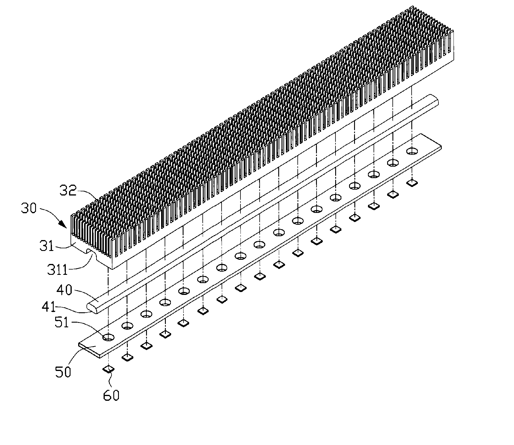
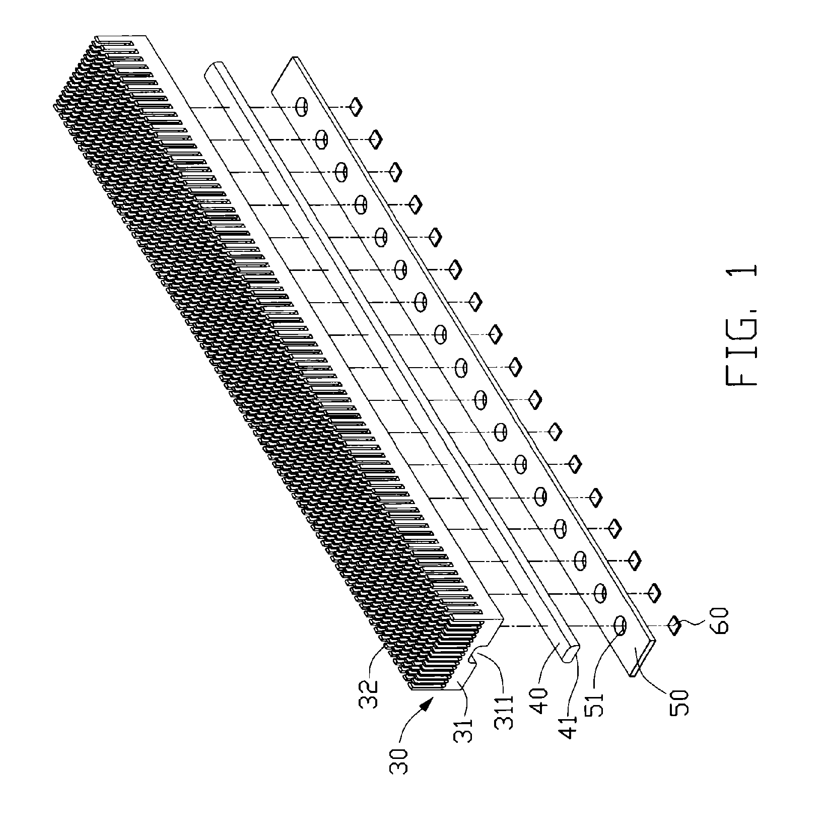
[0019]FIG. 1 illustrates an LED assembly in accordance with the present invention. The LED assembly includes a heat sink 30, a heat pipe 40, a circuit board 50, and a plurality of LED dies 60.

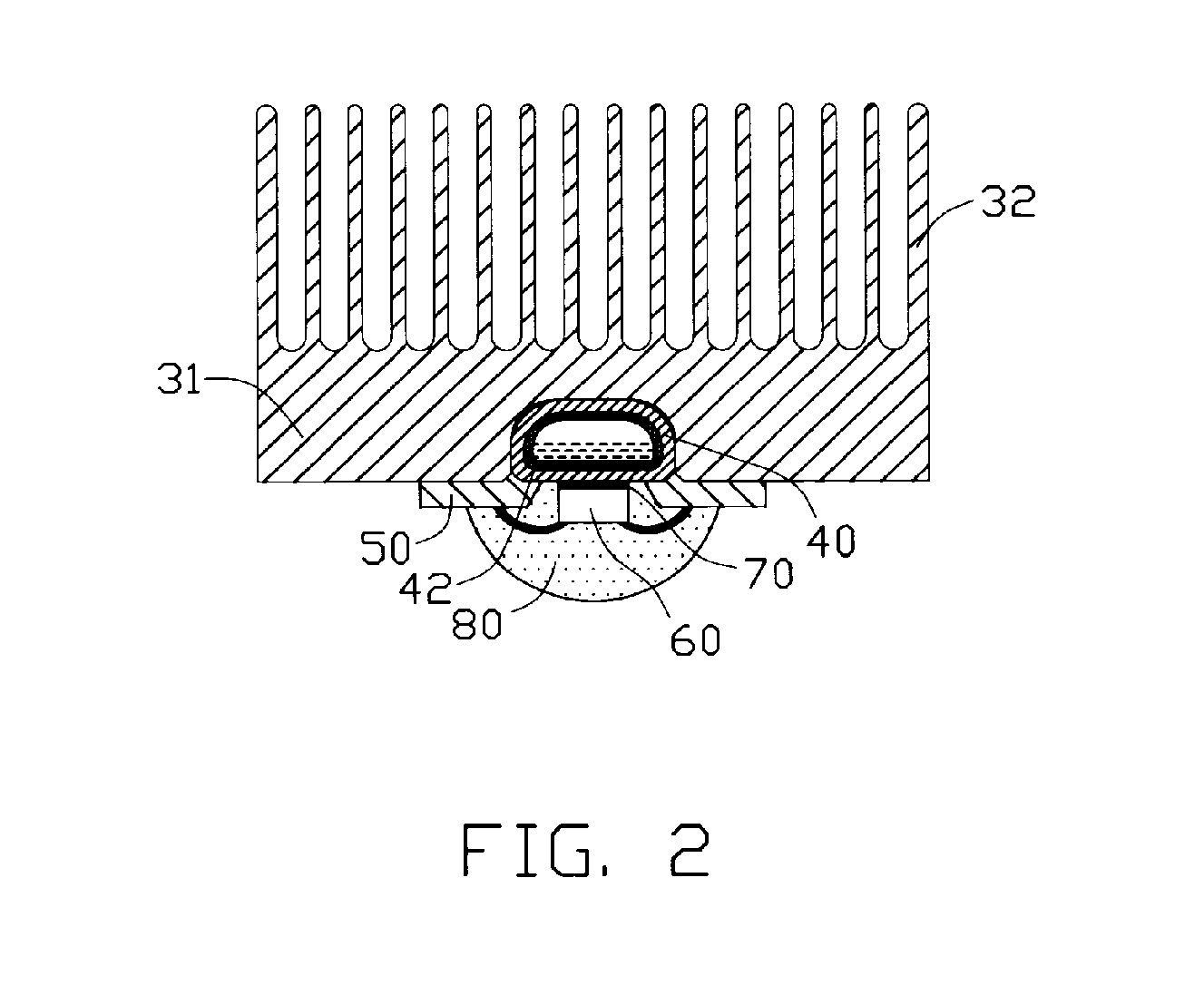
[0020] The heat sink 30 is made of highly thermally conductive material such as copper, aluminum, or their alloys. The heat sink 30 as shown in this embodiment is an extruded aluminum heat sink, including a chassis 31 and a plurality of pin fins 32 extending upwardly from the chassis 31. The chassis 31 defines an elongated groove 311 at a bottom surface thereof for receiving the heat pipe 40 therein. The groove 311 has a substantially rectangular shape.

[0021] The heat pipe 40 is a heat transfer device having a relatively high heat transfer capability due to a phase change mechanism it adopts. The heat pipe 40 has the advantage of low thermal resistance and is capable of transferring a large amount of heat while maintaining a low temperature gradient between different sections thereof. In this ...

second embodiment

[0026]FIG. 3 illustrates the present LED assembly, in which a plurality of recesses 43 are defined at the bottom surface 41 of the heat pipe 40a whereby the LED dies 60 are respectively received in the recesses 43 when they are mounted to the heat pipe 40a. Due to the presence of the recesses 43, the LED dies 60 and the heat pipe 40a are capable of being assembled in a more compact manner.

[0027] Apparently, in order to increase the heat dissipation efficiency for the LED assembly, multiple heat pipes 40 can be used. For example, two or more heat pipes 40 can be thermally attached to the chassis 31 of the heat sink 30.

[0028]FIG. 4 illustrates a third embodiment of the present LED assembly, in which a vapor chamber-based heat spreader 100 is provided. The heat spreader 100 has a much larger size than the heat pipe 40 shown in the first embodiment. The heat spreader 100 has a top surface from which a plurality of fins 34 extend upwardly and a flat bottom surface to which a circuit boa...

fifth embodiment

[0030]FIG. 6 shows the present LED assembly. The LED assembly in this embodiment employs a liquid cooling system to dissipate the heat generated by the LED dies 60. The liquid cooling system includes a cold plate 200 through which a working fluid such as water (hereinafter as “coolant”) is circulated, a pump 210, a heat exchanger 230 and a plurality of connecting pipes 220. In this embodiment, the circuit board 50c defines a plurality of rows of through holes 51 therein. The cold plate 200 defines a flow channel 201 therein for passage of the coolant. The flow channel 201 is wave-shaped in order to increase heat exchange area between the coolant and the cold plate 200. The LED dies 60 are respectively received in the through holes 51 of the circuit board 50c and are maintained in thermal and mechanical contact with a top surface of the cold plate 200, either directly or via a layer of TIM. As the coolant passes through the flow channel 201, it receives the heat generated by the LED ...


PUM


Abstract

A light-emitting diode (LED) assembly and a method for fabrication thereof are disclosed. The LED assembly includes a heat-absorbing member in which a working fluid is provided, an LED die (60) directly attached to the heat-absorbing member, and a heat-dissipating member thermally attached to the heat-absorbing member. The heat-absorbing member absorbs heat via the working fluid from the LED die and transfers the heat to the heat-dissipating member for dissipation. The method involves directly attaching the LED die to the heat-absorbing member.

Description

FIELD OF THE INVENTION [0001] The present invention relates generally to light-emitting diode (LED) assemblies, and more particularly to an LED assembly with improved heat dissipation ability so that heat generated by the LEDs of the assembly can be effectively removed. The present invention relates also to a method of packaging the LEDs. DESCRIPTION OF RELATED ART [0002] Light-emitting diode (LED) is a highly efficient light source currently used widely in such field as automobile, screen display, and traffic light indication. When the LED operates to give off light, heat is accordingly produced. If not rapidly and efficiently removed, the heat produced may significantly reduce the lifespan of the LED. [0003]FIG. 7 shows an LED module 10 mounted to a circuit board 18 in accordance with related art. The LED module 10 includes an LED die 11, a packaging layer 12, and a pair of conductive pins 14, 15. The LED die 11, which is placed in a recess defined in the conductive pin 15, is pro...

Claims


Application Information

Patent Timeline
Patent Type & Authority Applications(United States)
IPC IPC(8): H01J61/52H01J7/24H01J1/02H01L33/64
CPCF21K9/00F21V29/004F21V29/006F21V29/30F21Y2101/02H01L33/648F21V29/83H01L2224/48247H01L2224/48091F21V29/80F21V29/74H01L2924/00014F21V29/51F21V29/56F21Y2115/10
Inventor HU, TSENG-HSIANGHSIEH, YIH-JONGTAN, LI-KUANG
Owner HON HAI PRECISION IND CO LTD
Why Eureka
Try Eureka