Optical autodiscovery for automated logical and physical connectivity check between optical modules

Active Publication Date: 2007-04-26
INFINERA CORP
View PDF14 Cites 17 Cited by
  • Summary
  • Abstract
  • Description
  • Claims
  • Application Information

AI Technical Summary

Benefits of technology

[0023] Also, the principals of this disclosure can be extended to the identification as to a proper optical module connection may be the identification of the second optical module by the first optical module where the first module identifies the second module as an incorrect second optical module. This is particularly true in the case where the first optical module not only transmits, via patching, an optical signal or an OCG signal to the second optical module, but also in the second optical module transmits, via patching, an optical signal or an OCG signal to the second optical module that are proper for that module. Such a particular case is where the first optical module is an optical transceiver. However, the need of identification of the second optical module by the first optical module can be resolved by employing a duplex fiber connection for patching which allows checking for proper module identification in only one transmit direction between the first and second optical modules under the assumption that the other or opposite transmit direction is the same for the dual fiber port at the second optical module.

Problems solved by technology

First, connecting a first optical module to an incorrect port of a second optical module.
Second, connecting a first optical module to an incorrect second optical module or vice versa.
Third, connecting a first optical module of a first product generation to a second and incorrect optical module of a second product generation or vice versa.
However, once an appropriate first optical module has been associated with the predetermined port of the second optical module, then, the second optical module will not accept any other first optical module into that port even if another such first optical module has the same optical signal type or OCG signal type.

Method used


Image

  • Optical autodiscovery for automated logical and physical connectivity check between optical modules
  • Optical autodiscovery for automated logical and physical connectivity check between optical modules
  • Optical autodiscovery for automated logical and physical connectivity check between optical modules

Examples


Embodiment Construction

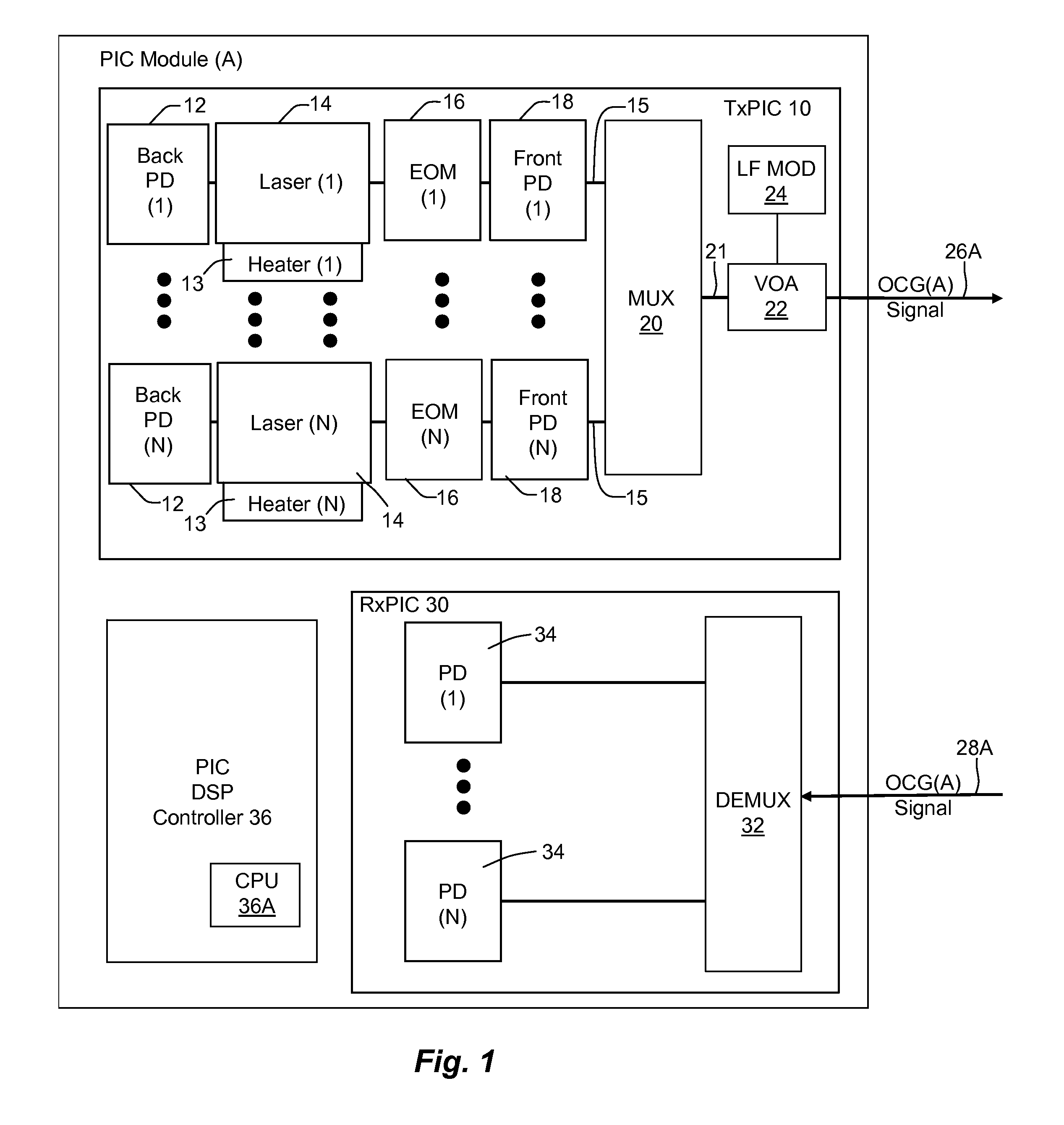
[0039] Before delving into the optical autodiscovery embodiments of this disclosure, an explanation of the exemplary modules in the implementation of the disclosed embodiments should be first explained. Reference is first made to FIG. 1 which discloses a photonic integrated circuit (PIC) group designated as PIC module A. PIC module A comprises a chip set of two PIC chips. Although the chip circuits could, alternatively, be integrated on a single chip. The transmitter PIC or T×PIC chip 10 contains a group of optical signal channels (1) to (N) where each channel 15 minimally includes a laser 14 and an electro-optical modulator (EOM) 16. The lasers (1) . . . (N) may each have an associated heater 13 which is control via a wavelength locker (not shown) to maintain a peak wavelength forming a wavelength grid of signal channels 15 across the channel array of T×PIC 10. Each channel 15 may include additional electro-optic elements, such as shown here comprising back and front monitoring pho...


PUM


Abstract

Optical autodiscovery is provide between two optical modules to insure that when an optical signal is coupled between the two optical module, the optical signal from a first module does not interfere with operation of a second module. The autodiscovery is implemented by sending an optical identification signal from the first optical module via the coupling to the second optical module from which signal, the second optical module can verify and determined acceptance of the coupled first optical module. During this autodiscovery process, the optical identification signal from the first optical module may be attenuated or shifted in optical spectrum so as not to interfere with the operation of the second optical module. Autodiscovery may also be employed in cases where a first optical module is to receive an optical signal from a second module.

Description

REFERENCE TO RELATED APPLICATION [0001] This application claims priority to provisional application, Ser. No. 60 / 695,508, filed Jun. 30, 2005, which application is incorporated herein by its reference in its entirety.INVENTORY OF TERMINOLOGY TERMS [0002] BMM—Band Multiplexer Module. There may be one for C Band and one for the L Band. [0003] Channels—A signal channel that minimally includes a modulated source. The channel may be in discrete form or in integrated form. In integrated form in a T×PIC, there is a plurality of modulated signal channels each having a modulated source of different emission wavelength. The outputs of the signal channels are coupled to an integrated combiner which provides a combined output signal of the channel signals. [0004] DLM—Digital Line Module. A substantially line side module that includes a PIC module having a T×PIC and R×PIC. [0005] EMS—Element management system basically comprising software to operate a management and control module (MCM). [0006] ...

Claims


Application Information

Patent Timeline
Patent Type & Authority Applications(United States)
IPC IPC(8): G02B6/00
CPCH04J14/0227H04J14/0241H04J14/0221H04J14/0264H04J14/0265H04J14/0275H04J14/0276H04J14/0258
Inventor MITCHELL, MATTHEW L.TAYLOR, ROBERT B.HAND, STEVEN JOSEPHMURPHY, DANIEL P.
Owner INFINERA CORP
Why Eureka
Try Eureka