Dual entry collection device for breath analysis

a collection device and breathalyzer technology, applied in the field of new breathalyzers and new methods for breath collection and analysis, can solve the problems of inconvenient use, inability to accurately measure, and inability to accurately measure, and achieve the effects of improving sanitation, rapid use by multiple users, and accurate measuremen

Inactive Publication Date: 2007-04-26
SHAW DAVID I HUNG
View PDF14 Cites 109 Cited by
  • Summary
  • Abstract
  • Description
  • Claims
  • Application Information

AI Technical Summary

Benefits of technology

[0017] The methods and apparatus of the present invention thus provide superior sanitation relative to closed-flow breathalyzers because, unlike closed-flow breathalyzers, the methods and apparatus of the present invention do not require user mouth contact. Consequently, the methods and apparatus of the present invention do not require regular cleaning or part replacement. Advantageously, in some embodiments, the breathalyzers of the present invention have a symmetrical design that affords ambidextrous use. Also, advantageously, the dual entry design of breath collection devices in accordance with the present invention are self-purging. This means that any lingering breath sample from a previous use is cleared out of the device prior to a subsequent use to ensure accurate measurement. In embodiments where the dual entry breathalyzer of the present invention is self-purging and ambidextrous, the breathalyzer can be passed around quickly without reorientation or shaking to clear out residual breath from previous tests. The design allows for rapid use by multiple users without the need for replacing mouthpieces or the inconvenience of rotation or reorientation after a hand-to-hand exchange.
[0018] The methods and apparatus of the present invention are also superior relative to the open-flow breathalyzers. An open-flow breathalyzer is designed such that the breath sample is directly blown onto a sensor or a sensor behind a grill. No means are taken to stabilize the breath flow. Consequently, breath measurements by the open-flow breathalyzers are typically inaccurate and inconsistent. In some embodiments of the present invention, one or more sensors are placed between two breathing entries of a collection tube, either embedded within the tube or inside a device that is in fluid communication with the collection tube. Breath samples taken in at either end of the collection tube travels some distance through the tube and stabilizes inside the device before reaching the one or more sensors. Because of this, the apparatus of the present invention provide accurate measurements of characteristics of a user such as blood alcohol level.

Problems solved by technology

However, the drawback with closed-flow breathalyzers is that they are inconvenient to use.
The inherent length of the straw or mouthpiece and the need for either a disposable straw or a replaceable mouthpiece cover compromises the compactness of a close-flow breathalyzer.
Closed-flow breathalyzers are often larger in size and cumbersome to handle, store and operate.
Furthermore, because breath samples are retained within the closed-form breathalyzer during measurement, residual air (e.g., ambient air or residual breath from previous users) may not be readily cleared out of such breathalyzers.
In worse-case situations, when residual breath samples from previous users are not efficiently purged out of the breathalyzer, breath measurements can be severely compromised in breath analysis of subsequent users.
Consequently, even though the open-flow breathalyzers eliminate the sanitary concerns associated with the closed-flow breathalyzers, measurements by an open-flow breathalyzers are usually inaccurate and inconsistent.
In both the closed-flow and open-flow breathalyzer designs, inadequate user instructions are typically provided.
As a result, such breathalyzers are often used in a manner that will not afford accurate results.
For example, a user will typically ignore or lose user instructions and blow into the breathalyzer in a manner that is not appropriate for the device thereby causing an in accurate measurement.

Method used


Image

  • Dual entry collection device for breath analysis
  • Dual entry collection device for breath analysis
  • Dual entry collection device for breath analysis

Examples


Embodiment Construction

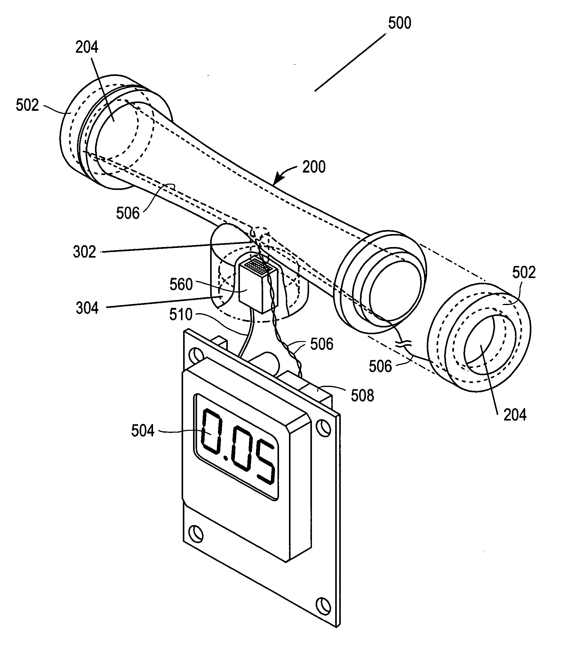
[0028] An apparatus in accordance with the present invention overcomes the disadvantageous features of existing breath analyzing apparatuses by introducing a dual entry collection device for more accurate, compact, convenient and sanitary use. In some embodiments, illumination features are added to the collection device in order to provide visual instruction on where to blow, when to blow into the apparatus, for how long to blow, and to inform the user of the outcome of the breath analysis.

[0029]FIG. 2 shows a perspective view of one embodiment of a breathalyzer collection device 200 in accordance with the present invention. The breathalyzer collection device 200 comprises dual entry 204 into a collection tube 202. It will be appreciated that both entries 204 are in fluid communication with each other. When a breath sample is introduced into first entry 204, residual ambient air or excess breath exits the opposing entry. Thus, each entry 204 also serves as an exit. The dual entry a...


PUM


Abstract

A breath analyzing apparatus comprising a collection tube that has at least a first and second breathing entry is provided. The collection tube is hollow such that the breathing entries are in fluid communication with each other. A sensor airway tube is fluidly joined to a central portion of the collection tube by a pin-hole orifice. With this design, a small portion of a breath sample is collected by the sensor airway tube when a user blows into either breathing entry and the majority of the breath sample is expunged out of the opposing breathing entry. The sensor airway tube either houses or is proximate to a sensor that senses the composition of the breath sample. Illumination is used to guide a user on where to blow, when to blow, for how long to blow, as well as to inform the user on the result of the breath analysis.

Description

FIELD OF THE INVENTION [0001] This invention relates to novel breathalyzers and new methods for breath collection and analysis. BACKGROUND OF THE INVENTION [0002] Breath samples of animals, especially human breath samples, contain alveolar air, the gas in the pulmonary alveoli where O2—CO2 exchange with pulmonary capillary blood occurs. The content of alveolar air provides information for disease diagnosis and drug monitoring. Thus breath collection and breath analysis is of importance. [0003] A blood alcohol analyzing unit, such as a breathalyzer, is one of the most commonly used devices for breath analysis. Available breathalyzers are classified into two types: the “closed-flow” type and the “open-flow” type, defined by whether a breath sample is retained in a closed chamber during analysis. A closed-flow breathalyzer, as illustrated for example in FIG. 1A, contains an easily recognizable inlet 102 for breath intake. In a closed-flow breathalyzer, the user's mouth or lips, or a st...

Claims


Application Information

Patent Timeline
Patent Type & Authority Applications(United States)
IPC IPC(8): A61B5/08
CPCA61B5/097G01N33/4972
Inventor SHAW, DAVID I-HUNG
Owner SHAW DAVID I HUNG
Why Eureka
Try Eureka