Modular system for customized orthodontic appliances

a technology of orthodontic appliances and modules, applied in the field of orthodontics, can solve the problems of not widely adopted andreiko et al. method, inability to take into account unpredictable events in the finish position of teeth, and little impact on the treatment of orthodontic patients

Inactive Publication Date: 2005-07-21
3M INNOVATIVE PROPERTIES CO
View PDF60 Cites 27 Cited by
  • Summary
  • Abstract
  • Description
  • Claims
  • Application Information

AI Technical Summary

Benefits of technology

[0015] For the front teeth, it is desirable to come up with a homogeneous inclination to avoid abrupt changes in inclination (i.e., changes in torque) from slot to slot in order to receive a smooth progression of the wire. In a wire of rectangular or square cross-sectional shape, one of the pairs of parallel opposite sides of the archwire is oriented substantially parallel to the tooth surface. Usually, this will be pair of parallel sides that has the greater width or height. This aspect of the invention enables the overall thickness of brackets to be substantially decreased as compared to prior art techniques, because it does not require a buildup of adhesive to make the slot lie in a horizontal flat plane when the bracket is attached, as found in the straight wire technique. The brackets and archwire design are particularly well suited for use in lingual orthodontics.
[0016] This reduction in thickness of the bracket, bracket bonding pad and archwire leads to several significant advantages as compared to prior art systems and satisfaction of a long-felt need in the art for a more satisfactory lingual orthodontic system. These advantages include decreased articulation problems, a pronounced decrease in tongue irritation, a decreased risk of bracket loss, increased positioning control for finishing since the reduced distance between wire and tooth results in more accurate tooth movement to the desired finish position, increased patient comfort, and increased hygiene conditions.
[0020] In still another aspect, a bracket is provided with an improved bracket bonding pad that makes the brackets essentially self positioning, that is, it may be uniquely located and positioned on the teeth in the correct location with a positive fit without the use of a jig or other bracket placement mechanism, such as the tray as proposed by Cohen, U.S. Pat. No. 3,738,005, or the jig of the Andreiko et al. patents. In particular, an improvement to a bracket having a bracket bonding pad is provided in which the bracket bonding pad has a tooth contacting surface of three-dimensional area extent conforming substantially exactly to the three-dimensional shape of the tooth where the pad is bonded to the tooth.
[0021] In one possible embodiment, the three-dimensional area extent is sufficiently large, and considerably larger than all bracket bonding pads proposed in the prior art, such that the bracket can be readily and uniquely placed by hand and located on the tooth in the correct location due to the substantial area extent corresponding to the three-dimensional surface of the tooth. The bracket is able to be bonded in place on the tooth without the assistance of a bracket placement aid such as a jig. In another possible embodiment, the area extent covers a cusp or a portion of a cusp to enable the bracket to uniquely placed on the tooth.

Problems solved by technology

The method of Andreiko et al. has not been widely adopted, and in fact has had little impact on the treatment of orthodontic patients since it was first proposed in the early 1990s.
There are a variety of reasons for this, one of which is that the deterministic approach proposed by Andreiko et al. for calculating tooth finish positions does not take into account unpredictable events during the course of treatment.
It is obvious that every fraction of a mm added to appliance thickness significantly increases patient discomfort.
Especially with lingual brackets (bracket bonded to the lingual surface of the teeth), articulation problems arise, and the tongue is severely irritated for several weeks after bonding.
The tooth surfaces next to these adhesive pads are difficult to clean, thus serving as collecting point for bacteria and causing gingival inflammation.
The further the archwire is away from the tooth surface, the more difficult it is to achieve a precise finishing position for each tooth.
An error of only 10° in torque (rotation around the wire axis) may well induce a vertical error in tooth position of more than 1 mm.
Another significant disadvantage of thick brackets, especially when bonding lingually, arises when the front teeth are severely crowded (which is often the cause for orthodontic treatment).
Crowding also creates problems for labial brackets.
Geometrical considerations dictate that this constriction problem becomes worse as the thickness of the bracket / bracket bonding pad / adhesive combination increases.
Another problem in orthodontics is to determine the correct bracket position.
So the task to locate the brackets in a manner that a flat planar archwire drives teeth to the correct position requires a lot of experience and visual imagination.
The result is that at the end of treatment a lot of time is lost to perform necessary adjustments to either bracket position or wire shape.
Obviously, the transfer tray used for initial bonding will not fit any more as teeth have moved.
While it is possible to cut the tray (such as described in WO 01 / 80761) into pieces and use just the one section that is assigned to the bracket that came off, to replace the bracket the reliability of this procedure is limited, as a small piece of elastic material is not adequate to securely position a bracket.
It may therefore be required to create a new transfer tray adapted to the current tooth position using a costly lab process.

Method used


Image

  • Modular system for customized orthodontic appliances
  • Modular system for customized orthodontic appliances
  • Modular system for customized orthodontic appliances

Examples


Embodiment Construction

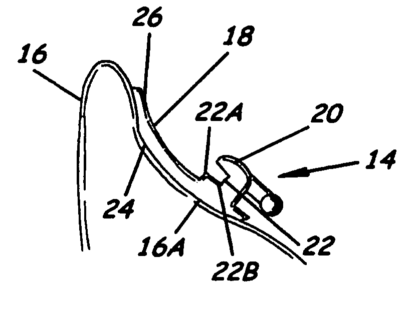
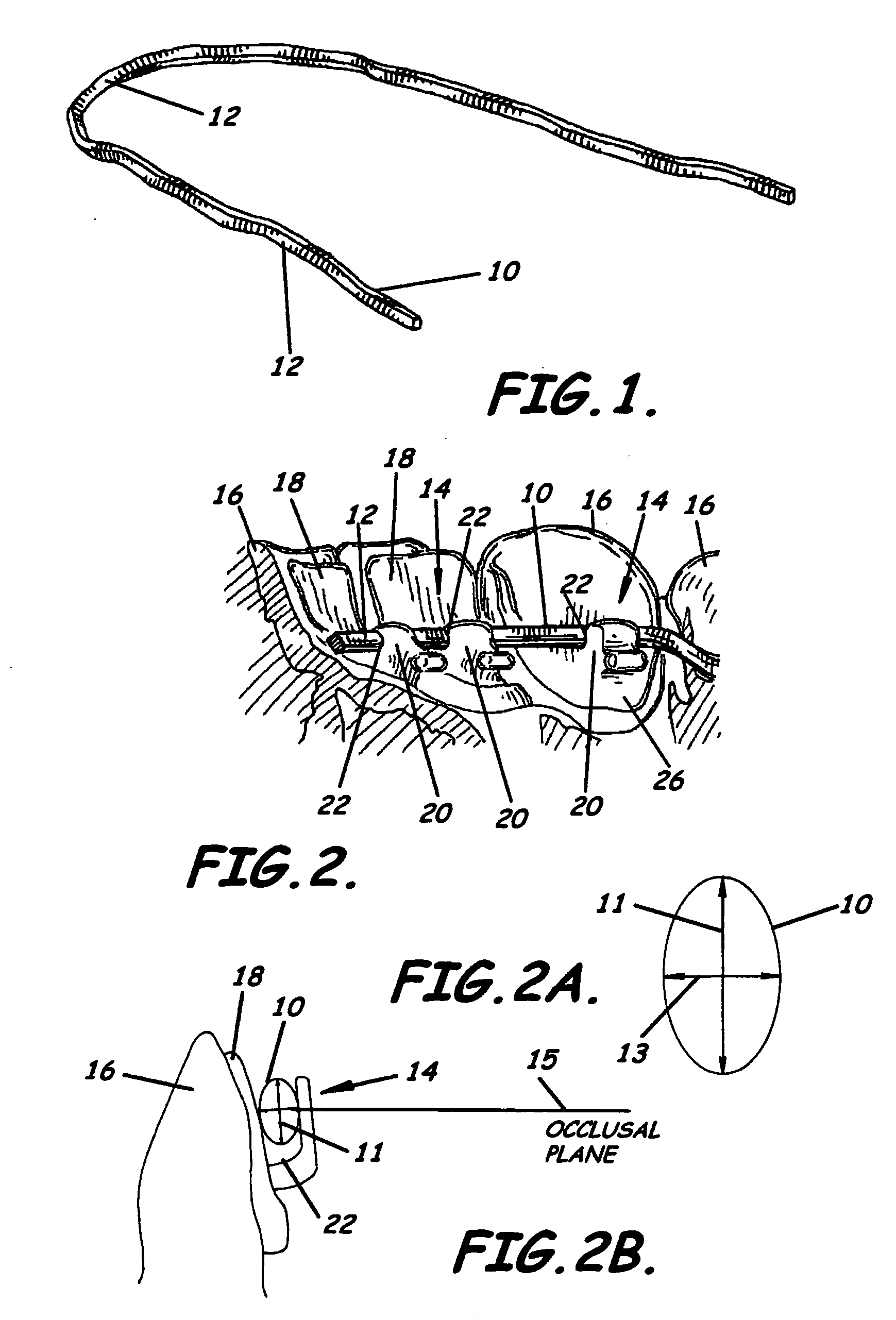
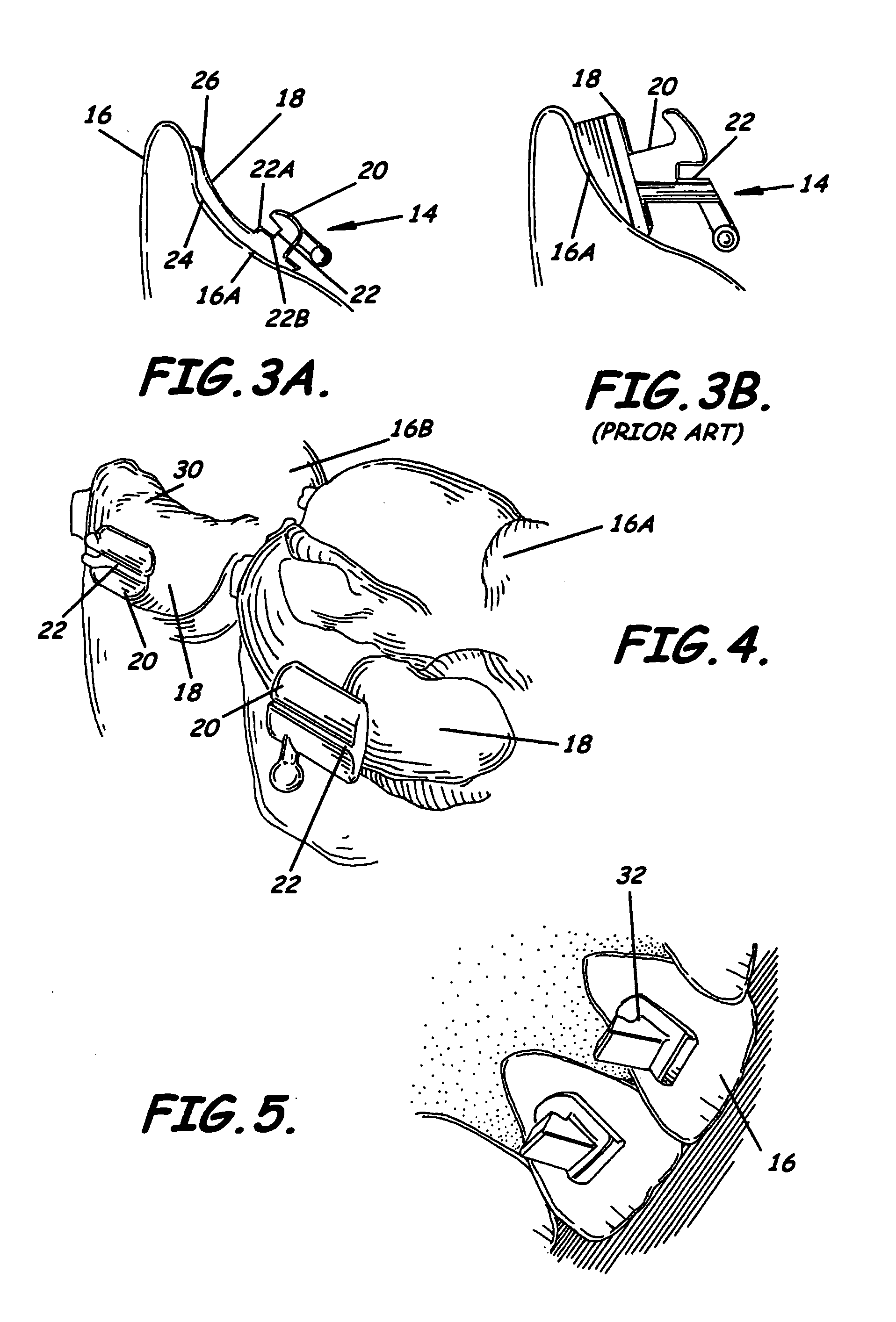
[0055] Bracket Slot Parallel to Tooth Surfaces and Canted Archwire

[0056] As noted earlier, in the straight wire approach to orthodontics practiced today, the basic design of orthodontic wires in the prior art is a flat, planar shape. All the slots of the brackets, when the teeth are moved to the desired occlusion, lie in a plane. Accordingly, the archwire itself, which is of rectangular cross-section, has a flat, planar configuration. This is also the case for wires to be used with the CONSEAL™ brackets mentioned previously. While the cross-section of the wire is oriented in a vertical manner (the longer side of the wire is vertical), the archwire still forms a plane that is substantially parallel to the occlusal plane and the orientation of the cross-section is maintained along the wire. The primary reason for this phenomenon is the ease of industrial manufacturing of archwires of flat planar configuration. In a first aspect of the invention, we propose a significant departure fro...


PUM


Abstract

A set of customized orthodontic brackets are provided with slots that are arranged substantially parallel to the tooth surface. The archwire, in an as-manufactured condition, has a portion of substantial arcuate extent, which is canted relative to the occlusal plane. The brackets are designed on a computer as a combination of three-dimensional virtual objects comprising the virtual bracket bonding pad and a separate virtual bracket body retrieved from a library of virtual bracket bodies. The virtual brackets can be represented as a file containing digital shape data and exported to a rapid prototype fabrication device for fabrication of the bracket in wax or other material and casting the wax prototype in a suitable alloy. Other manufacturing techniques are also contemplated, including milling and laser sintering.

Description

BACKGROUND OF THE INVENTION [0001] A. Field of the Invention [0002] This invention relates generally to the field of orthodontics. More particularly, the invention relates to methods for designing and manufacturing brackets and archwires for purposes of straightening the teeth of a patient, and novel brackets and archwires made in accordance with the methods. The invention is useful for orthodontics generally. It can be employed with particular advantage in lingual orthodontics, that is, where the orthodontic appliance is attached to the lingual surface of the teeth for aesthetic reasons. [0003] B. Description of Related Art [0004] A widely used method to straighten or align teeth of a patient is to bond brackets onto the teeth and run elastic wires of rectangular cross-sectional shape through the bracket slots. Typically, the brackets are off-the-shelf products. In most cases, they are adapted to a certain tooth (for instance an upper canine), but not to the individual tooth of a s...

Claims


Application Information

Patent Timeline
Patent Type & Authority Applications(United States)
IPC IPC(8): A61C7/00A61B19/00A61C7/14A61C7/28A61C13/00G06F17/50
CPCA61C7/002A61C7/145A61C7/148A61C7/16A61C7/141A61C7/20A61C13/0004B33Y80/00B33Y50/00A61C3/00
Inventor WIECHMANN, DIRKPAEHL, RALFWEISE, THOMASRUBBERT, RUDGER
Owner 3M INNOVATIVE PROPERTIES CO
Why Eureka
Try Eureka