
Servo motor stop controlling method and servo motor controller

a technology of servo motor and control method, which is applied in the direction of motor/generator/converter stopper, electric programme control, dynamo-electric converter control, etc., can solve the problem of wave-like disturbance of the curve of the speed reduction characteristics, the acceleration torque immediately after the emergency stop becomes so large, and the speed reduction characteristics may be affected by vibration or shock. , to achieve the effect of shortening the stop time and reducing the stopping distan

Inactive Publication Date: 2007-05-03
FANUC LTD
View PDF8 Cites 34 Cited by
  • Summary
  • Abstract
  • Description
  • Claims
  • Application Information

AI Technical Summary

Benefits of technology

[0010] It is an object of the present invention to solve the above-described problem and to provide a servo motor stop controlling method and a servo motor controller that is capable of stopping the rotation of a servo motor, in case of an emergency stop, in a shorter stop time with a reduced stopping distance.

Problems solved by technology

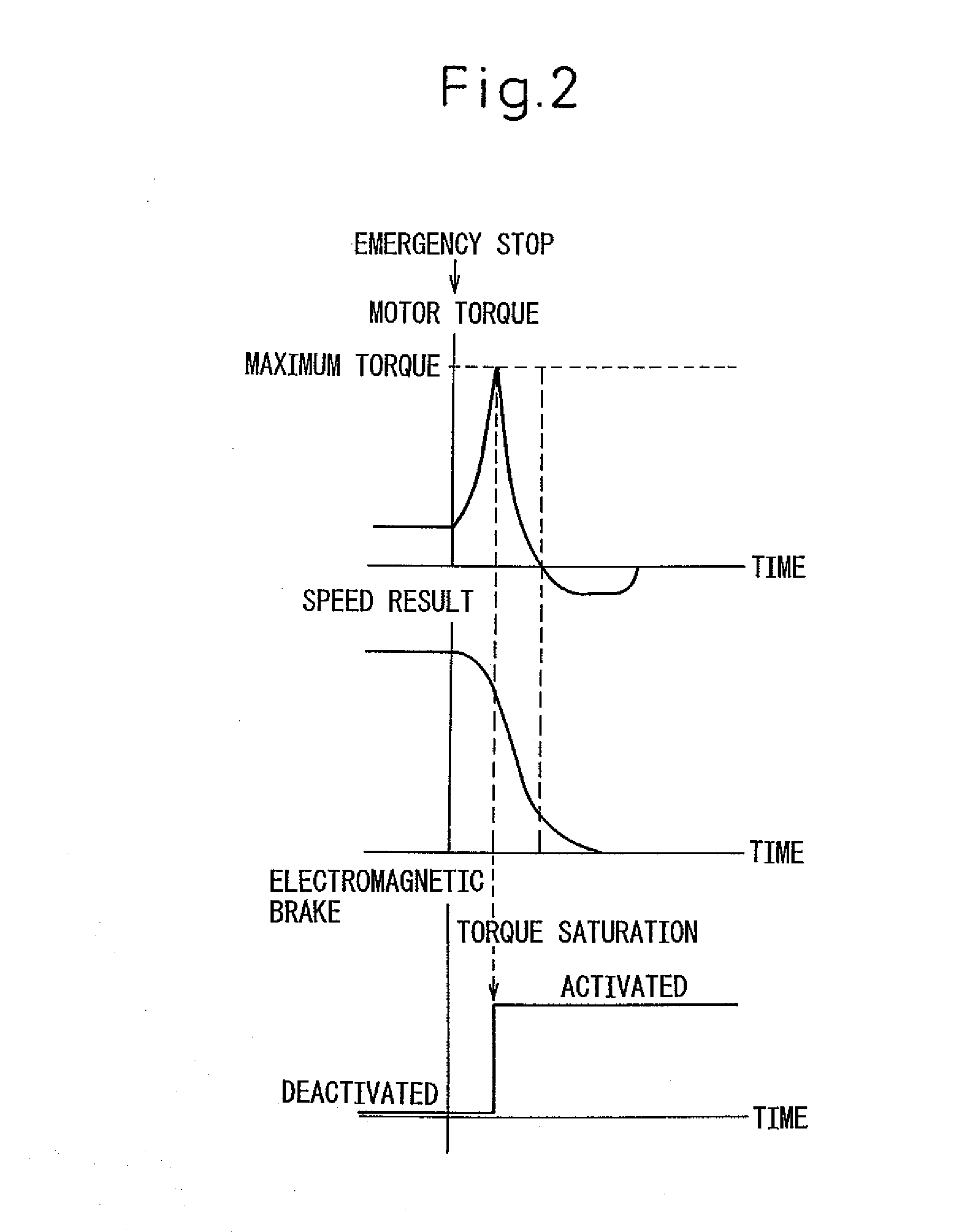
As shown in FIG. 4, although the stopping time T can be reduced by activating both a dynamic brake and an electromagnetic brake at the time of an emergency stop, it has a problem that a decelerating torque immediately after the emergency stop becomes so large that vibration or shock may be induced during speed reduction.
A wave-like disturbance in the curve of the speed reduction characteristics are caused by the inadequate torque of the servo motor.
That is, the decelerating torque required for speed reduction of the servo motor by means of speed control reaches the maximum allowable torque that is intrinsic to the individual servo motor (saturation of the decelerating torque), and thereby it become maybe difficult to accurately control the servo motor.
It can be seen that the resulting speed shows a disturbance and the stopping time is longer.
However, there is a problem that, when a servo motor is quickly stopped from the state of high speed or high load of the servo motor, the decelerating torque saturates and the servo motor may become difficult to accurately control the servo motor and give rise to vibration and delay in response to a control command.
Thus, although, in an emergency stop from the state of low speed or low load, it is possible to stop the rotation of servo motor in a short time period by speed control, there is a problem that, in an emergency stop from the condition of nearly maximum speed or maximum load, the servo motor may be unable to provide adequate torque and thus may give rise to vibration or delay in the response to a control signal.

Method used


Image

  • Servo motor stop controlling method and servo motor controller
  • Servo motor stop controlling method and servo motor controller
  • Servo motor stop controlling method and servo motor controller

Examples


Embodiment Construction

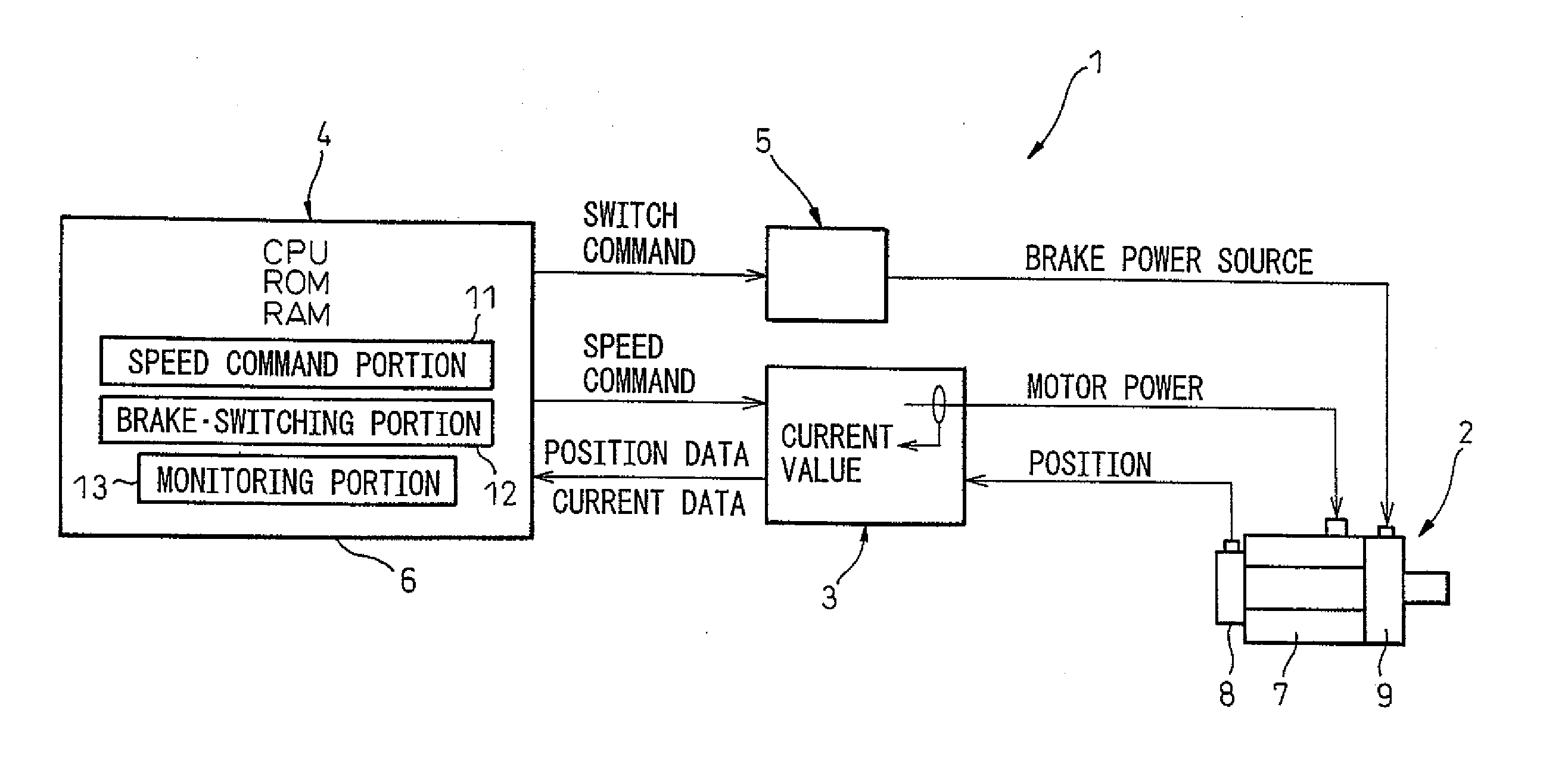
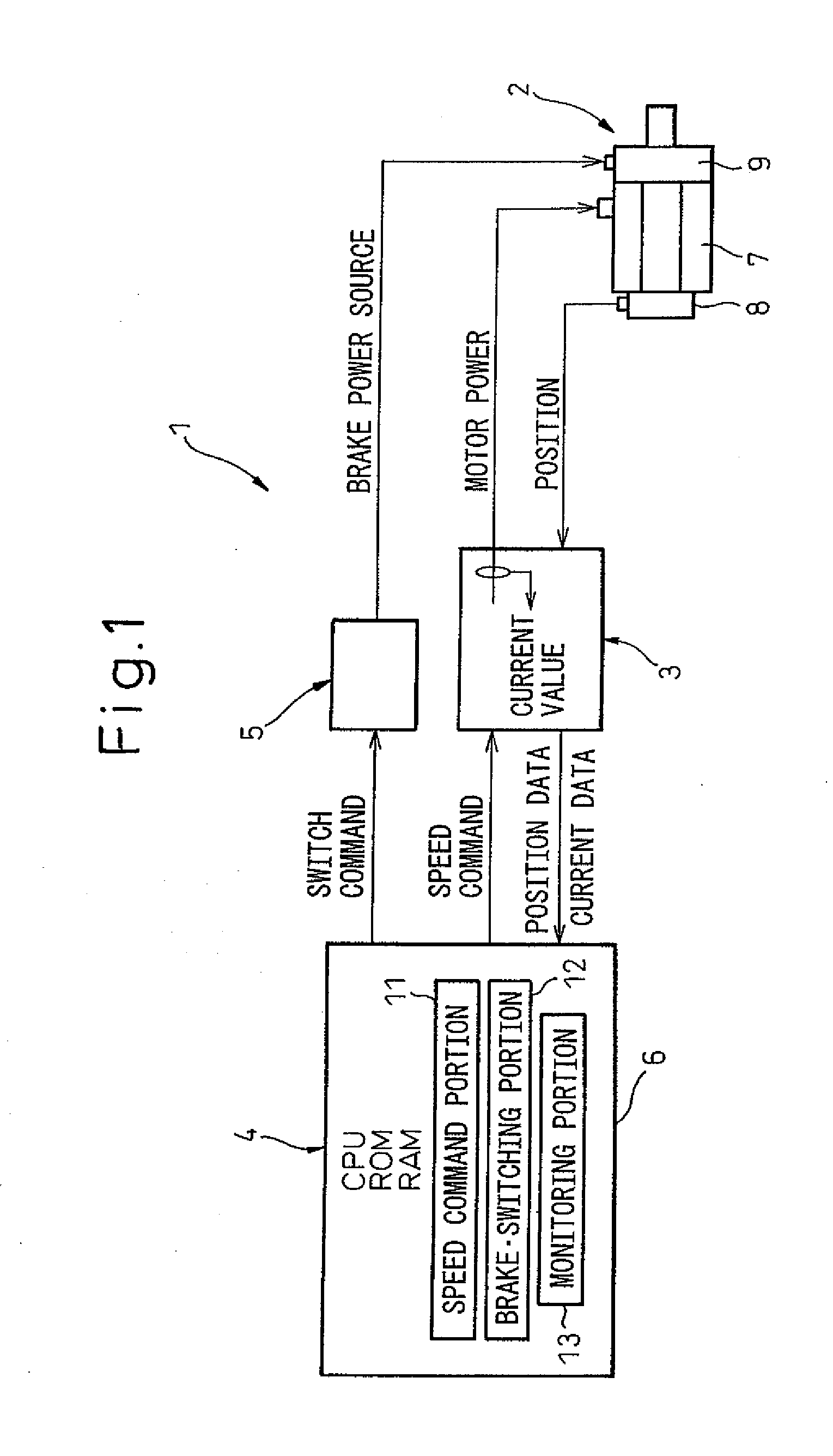
[0020] Next, the present invention will be described, in detail, with reference to drawings showing specific examples of embodiments thereof. FIG. 1 is a view showing the construction of a servo motor controller according to the present invention.

[0021] A servo motor controller 1 according to the present embodiment is a controller for controlling a servo motor 2 for rotationally driving a joint portion of an unshown multi-joint type industrial robot, including a servo amplifier 3 for supplying a controlled current to the servo motor 2, a motor control section 4 electrically interconnected to the servo motor 2 via the servo amplifier 3, and a braking circuit 5 controlled by the motor control section 4 for ON / OFF switching of an electromagnetic brake (brake) 9.

[0022] The servo motor 2 comprises a motor main body 7, an encoder 8 as a position detector for detecting the position information of the motor, and an electromagnetic brake 9 which functions as a frictional brake and a holdin...


PUM


Abstract

A servo motor controller is provided with a motor control section for controlling a servo motor provided with a brake. The motor control section includes a speed command portion for outputting a speed command to increase or reduce the rotation of the servo motor, and a brake switching portion for outputting switch command for a braking circuit to switch the brake, wherein the brake is activated during speed reduction of the servo motor by the speed command portion, whereby a rotation of the servo motor is stopped. The motor control section further includes a monitoring portion for monitoring whether or not the decelerating torque of the servo motor during speed reduction exceeds a set value that has been set equal to or lower than a maximum allowable torque of the servo motor in the motor control section.

Description

RELATED APPLICATION [0001] The present application is based on, and claims priority from, Japanese Application Number 2005-295053, filed Oct. 7, 2005, the disclosure of which is hereby incorporated, by reference, in its entirety.BACKGROUND OF THE INVENTION [0002] 1. Field of the Invention [0003] The present invention applies generally to a system using a servo motor, such as an industrial robot, a machine tool, a positioning device, etc. More particularly, the present invention relates to a servo motor stop controlling method and a servo motor controller in which the rotation of a servo motor provided with a brake is stopped by means of speed control. [0004] 2. Description of the Related Art [0005] Conventionally, in various systems comprising a servo motor, in order to stop the rotation of a servo motor safely and in as short a time period as possible at the time of an emergency stop, a dynamic brake utilizing regenerative energy of the servo motor and an electromagnetic brake are ...

Claims


Application Information

Patent Timeline
Patent Type & Authority Applications(United States)
IPC IPC(8): H02P3/00G05B19/19H02P3/16H02P3/26H02P25/098H02P29/00H02P29/10
CPCH02P3/04H02P3/16H02P3/26
Inventor HASHIMOTO, YOSHIKITANABE, YOSHIKIYOHAMADA, TOSHIHIKO
Owner FANUC LTD
Learn More