Robust detection of strain with temperature correction

a temperature correction and robust detection technology, applied in special purpose recording/indication apparatus, instruments, magnetic property measurements, etc., can solve problems such as the change of ac output voltage, and achieve the effect of increasing strength

Active Publication Date: 2007-05-03
BWI
View PDF4 Cites 22 Cited by
  • Summary
  • Abstract
  • Description
  • Claims
  • Application Information

AI Technical Summary

Benefits of technology

[0005] It is the object of the present invention to provide an apparatus for measuring a return signal of a magnetostrictive sensor that detects a force. The apparatus comprises a magnetostrictive sensor for generating a return signal in response to a force and including noise and an in-phase signal and a quadrature signal shifted ninety degrees from the in-phase signal and each are a function of the force detected by the sen

Problems solved by technology

Changes in the known inductance then cause an unba

Method used


Image

  • Robust detection of strain with temperature correction
  • Robust detection of strain with temperature correction
  • Robust detection of strain with temperature correction

Examples


Embodiment Construction

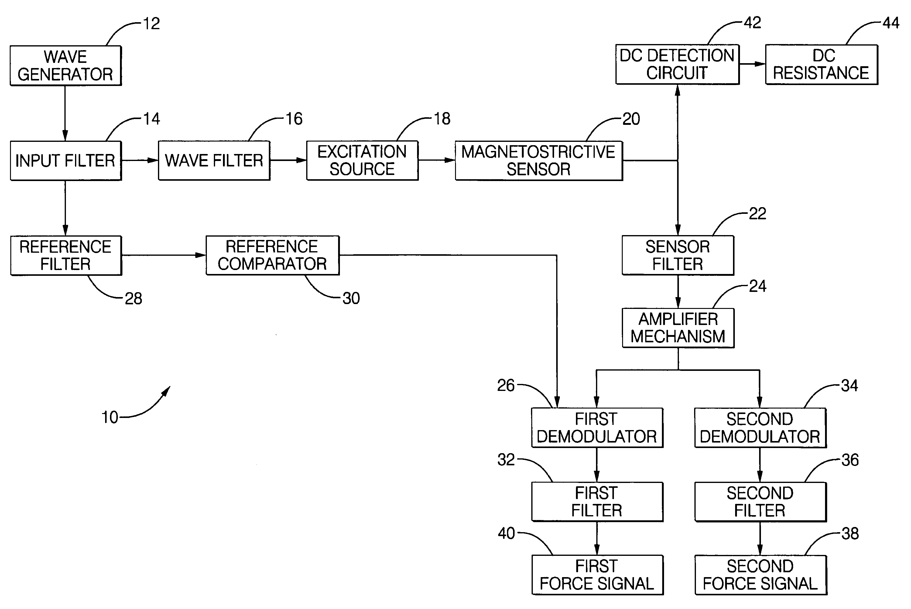
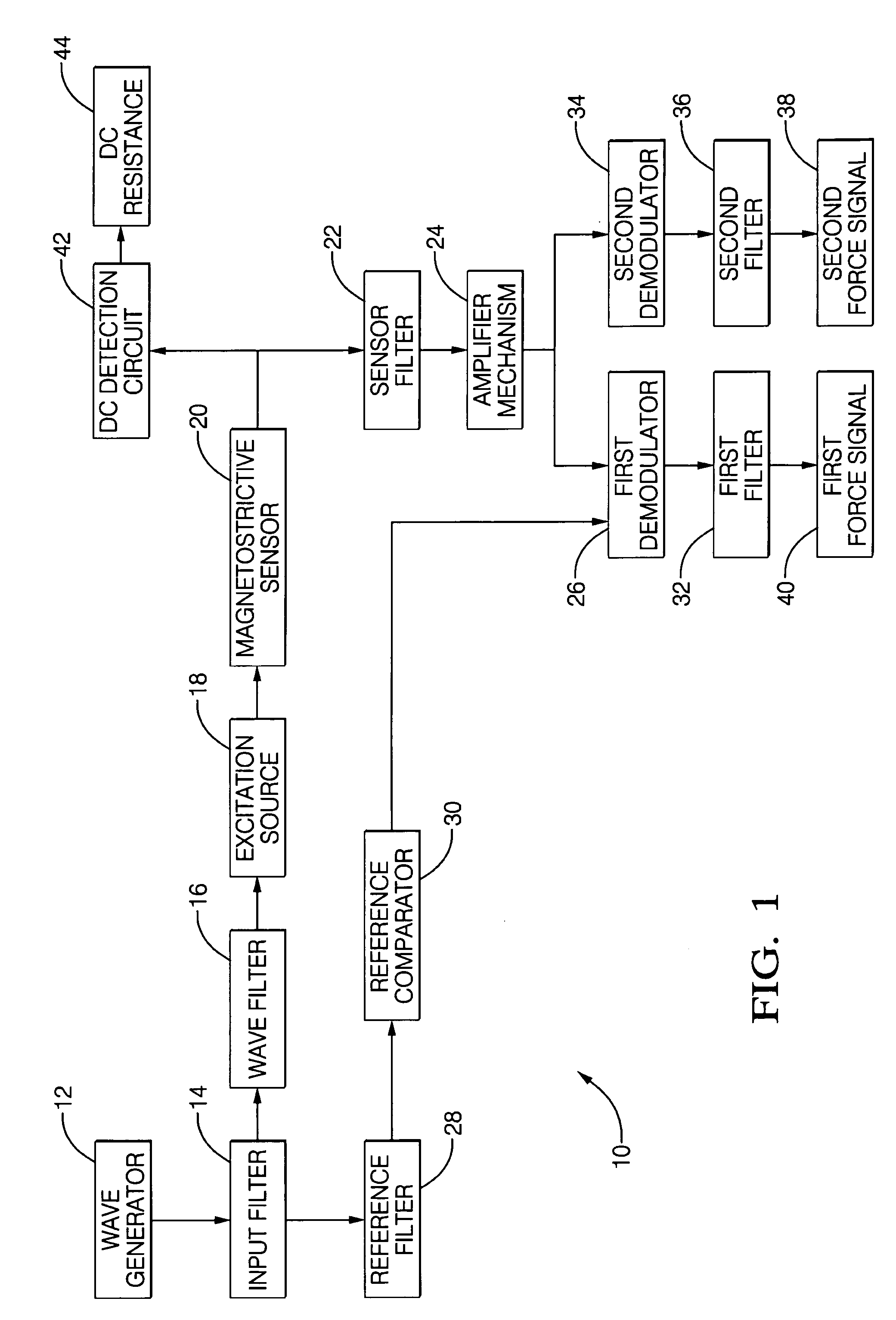
[0014] An apparatus for measuring a return signal of a magnetostrictive sensor 20 that detects a force is shown generally at 10 in FIG. 1. The apparatus 10 includes a wave generator 12 for generating an oscillating signal in the form of a sinusoidal wave which includes harmonics at a predetermined frequency of for instance between 1 Khz-100 kHz. An input filter 14 is coupled to the wave generator 12 for removing harmonics in the oscillating signal and any frequencies above the predetermined frequency. The cutoff frequency of the input filter 14 is configured to the predetermined frequency of the sinusoidal wave.

[0015] An excitation source 18 may be a current source or a voltage source which produces an excitation output. The excitation output includes an alternating voltage or an alternating current at the predetermined frequency for driving the sensor 20 in response to the sensor being subjected to a force. The utilization of the excitation source 18 introduces noise and may inclu...


PUM


Abstract

An apparatus (10) is set forth for measuring a return signal of a magnetostrictive sensor (20) that detects a force, torque, or pressure. The return signal includes noise, a DC resistance (44), an AC resistance and an inductance and the inductance is shifted ninety degrees from the AC resistance. The apparatus (10) includes a sensor filter (22) to remove the noise from the return signal. A sensor filter (22) shifts the return signal and more specifically, the inductance by an additional angle and the sum of the additional angle and the ninety degrees phase shift is defined as the final detection angle. To detect the inductance at the final detection angle, a wave filter (16) and a reference filter (28) shifts a reference signal by the final detection angle to trigger a first demodulator (26) to detect the inductance at the final detection angle. The inductance detected by the first demodulator (26) varies due to temperature. To remove the temperature from the measured inductance, the apparatus includes a DC detection circuit (42) to detect the DC resistance which is proportional to the temperature across the sensor (20). The DC resistance and the measure inductance are inserted into a correction equation to produce a corrected inductance which is independent of temperature. Instead of inductance, an AC resistance may be used in the equation.

Description

TECHNICAL FIELD [0001] The subject invention relates to an apparatus for measuring a return signal of a magnetostrictive sensor that detects a strain and a method for measuring an inductance or an AC resistance and a DC resistance across a coil of a magnetostrictive sensor that is subjected to a strain to produce a corrected inductance or an AC resistance which is proportional to the strain and is independent of temperature. BACKGROUND OF THE INVENTION [0002] Magnetostrictive sensors have proven to be effective in measuring force. By measuring the AC resistance or the inductance across a coil of the magnetostrictive sensor it is possible to determine the amount of force subjected to the sensor. Methods of measuring inductance have included the use of resonant circuits and impedance bridges. In a resonant circuit, the resonant frequency depends on inductance; a change in the latter results in changes to the frequency which can be measured with a digital counter or converted to an ana...

Claims


Application Information

Patent Timeline
IPC IPC(8): G01R33/18
CPCG01D3/036G01L1/127G01L1/125G01D5/485
Inventor OBERDIER, LARRY M.SCHROEDER, THADDEUSDISSER, ROBERT J.DEWAR, TINA M.BAUDENDISTEL, THOMAS A.LEQUESNE, BRUNOMORELLI, DONALD T.
Owner BWI
Why Eureka
Try Eureka