
Temperature compensation circuit for a surface acoustic wave oscillator

a surface acoustic wave and temperature compensation technology, applied in the direction of generator stabilization, electric apparatus, etc., can solve the problems of affecting the phase noise affecting the performance of the phase noise, and more conventional resonator technologies such as at-cut quartz crystals have not been fully successful

Inactive Publication Date: 2007-05-03
CTS CORP ELKHART
View PDF19 Cites 12 Cited by
  • Summary
  • Abstract
  • Description
  • Claims
  • Application Information

AI Technical Summary

Benefits of technology

The invention provides a circuit for compensating the frequency of a surface acoustic wave oscillator that is used in electronic devices. The circuit includes a temperature sensor, a conditioner, a reactance generator, and a resonator device. The conditioner filters the temperature sensor signal and sends it to the reactance generator, which generates a compensation signal. The resonator device produces a stable output frequency over a temperature range. The technical effect of this invention is to improve the accuracy and stability of the output frequency of the surface acoustic wave oscillator over a range of temperatures.

Problems solved by technology

For higher frequency applications now in demand, e.g., above 500 MHz, more conventional resonator technologies such as standard AT-cut quartz crystals have not been fully successful.
While crystal-based oscillators provide good frequency versus temperature characteristics, the multiplication of the crystal frequency creates adverse sub-harmonics and degrades phase noise performance.
While this technology requires no multiplication and hence does not result in any sub-harmonics or degradation in phase noise, the frequency versus temperature performance thereof is on the order of 2× to 10× worse than its uncompensated crystal counterpart.
Unfortunately, the device of Kinsman is not adapted to be efficiently manufactured in significant quantities because the mass production of temperature compensated SAW oscillators requires a circuit topology and method of temperature compensation which accounts for component tolerance variances between individual SAW resonators as well as other circuit components.

Method used


Image

  • Temperature compensation circuit for a surface acoustic wave oscillator
  • Temperature compensation circuit for a surface acoustic wave oscillator
  • Temperature compensation circuit for a surface acoustic wave oscillator

Examples


Embodiment Construction

Oscillator Circuit

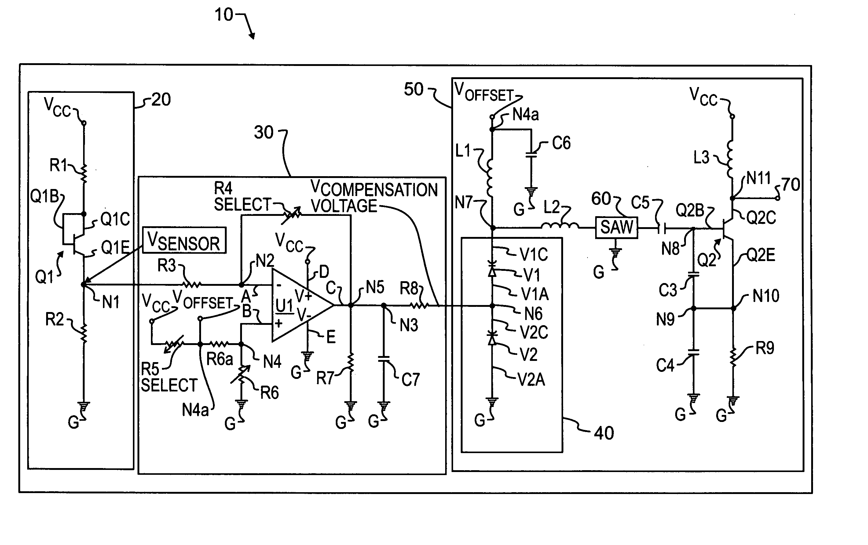
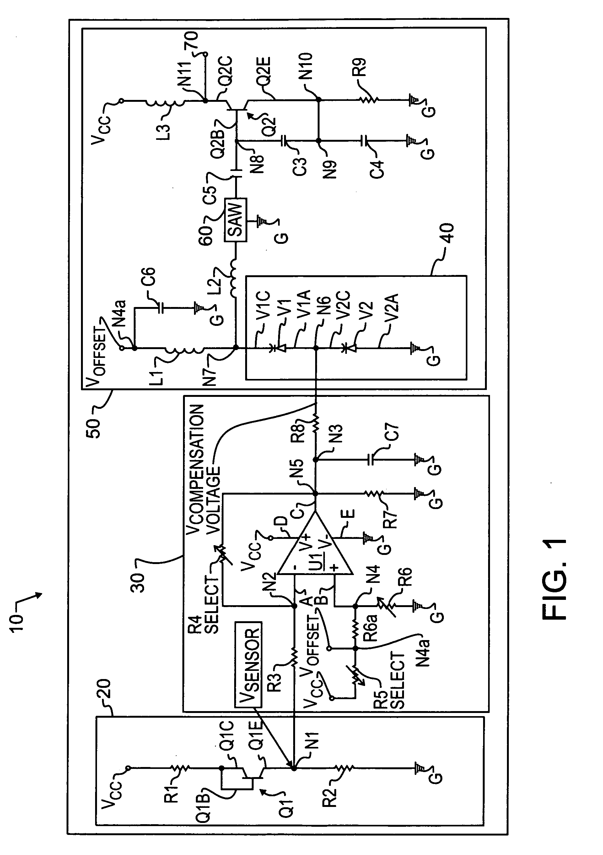
[0022]FIG. 1 is a schematic diagram of a surface acoustic wave oscillator 10 with a temperature compensation circuit in accordance with the present invention. Oscillator 10 includes a temperature sensor 20, a temperature signal conditioner 30, a reactance generator 40, an oscillator circuit 50, and a surface acoustic wave resonator (SAW) 60.

[0023] Temperature sensor 20 can comprise a transistor Q1 having a base Q1B, an emitter Q1E and a collector Q1C. The base Q1B is connected to collector Q1C. Collector Q1C is connected to a DC power source Vcc through a resistor R1. Power source Vcc is preferably set above Voffset and can be approximately 5 volts. Emitter Q1E is connected to node N1. Node N1 is connected to resistor R2. The other end of resistor R2 is connected to ground G.

[0024] Transistor Q1 is adapted to change output voltage in response to a change in temperature. The voltage developed at node N1 therefore is proportional to the temperature that transisto...


PUM


Abstract

A surface acoustic wave oscillator includes a temperature sensor adapted to generate a temperature sensor signal. A temperature signal conditioner is coupled to the temperature sensor. The temperature signal conditioner receives the temperature sensor signal and generates a conditioned temperature sensor signal. A reactance generator is coupled to the temperature signal conditioner. The reactance generator receives the conditioned temperature sensor signal and generates a compensation signal. A surface acoustic wave device is coupled to the reactance generator. An oscillator circuit is coupled to the surface acoustic wave device.

Description

FIELD OF THE INVENTION [0001] This invention relates to surface acoustic wave oscillators and, in particular, to temperature compensated high-frequency surface acoustic wave frequency oscillators. DESCRIPTION OF THE RELATED ART [0002] High capacity data networks rely on signal repeaters and sensitive receivers for low-error data transmission. To decode and / or cleanly re-transmit a serial data signal, such network components include components for creating a data timing signal having the same phase and frequency as the data signal. This step of creating a timing signal has been labeled “clock recovery.”[0003] Data clock recovery requires a relatively high purity reference signal to serve as a starting point for matching the serial data signal clock rate and also requires circuitry for frequency adjustment. The type, cost and quality of the technology employed to generate the high purity reference signal vary according to the class of data network application. For fixed large-scale in...

Claims


Application Information

Patent Timeline
Patent Type & Authority Applications(United States)
IPC IPC(8): H03L1/00
CPCH03L1/023
Inventor MEISSNER, VERN
Owner CTS CORP ELKHART
Learn More