Voltage controlled surface acoustic wave oscillator module

a voltage controlled surface and oscillator technology, applied in the field of oscillators, can solve the problems of critical handling of saw oscillator components, inability to fully realize the full success of more conventional resonator technologies such as standard at-cut quartz crystals, and high cost of manufacturing oscillator components

Active Publication Date: 2008-12-16
CTS CORP ELKHART
View PDF4 Cites 4 Cited by
  • Summary
  • Abstract
  • Description
  • Claims
  • Application Information

AI Technical Summary

Problems solved by technology

For higher frequency applications now in demand, e.g., above 300 MHz, more conventional resonator technologies such as standard AT-cut quartz crystals have not been fully successful.
Because even dust-size contamination of SAW resonators affects center frequencies, packaging and handling for SAW oscillator components is critical.
These special packaging and handling requirements not only contribute to the cost of manufacturing oscillator components but also limit efforts at reducing the overall module size.

Method used


Image

  • Voltage controlled surface acoustic wave oscillator module
  • Voltage controlled surface acoustic wave oscillator module
  • Voltage controlled surface acoustic wave oscillator module

Examples


first alternate embodiment

[0047]Referring to FIG. 7, a drawing of an alternative metal layer 50 for the substrate 12 is shown. Layer 50 can replace layer 25c shown in FIG. 5. Inner layer 50 has a top surface 51. A winding, serpentine-shaped circuit line 52 is mounted on surface 51. Other circuit lines 54 can also be mounted on surface 51. Circuit lines 54 can be connected with plated through-holes 24 in an appropriate configuration in order to connect oscillator 100.

[0048]Circuit line 52 has a serpentine or looped shape and is designed to have sufficient distributed self-inductance to replace inductor L1 shown in FIG. 2 and mounted on top surface 15. Circuit line 52 can also be connected with plated through-holes 24 in an appropriate configuration in order to replace discrete inductor L1. The use of an interior circuit line 52 results in a more compact module and eliminates the cost of purchasing and mounting an exterior inductor L1 to the top surface 14 of substrate 12.

second alternate embodiment

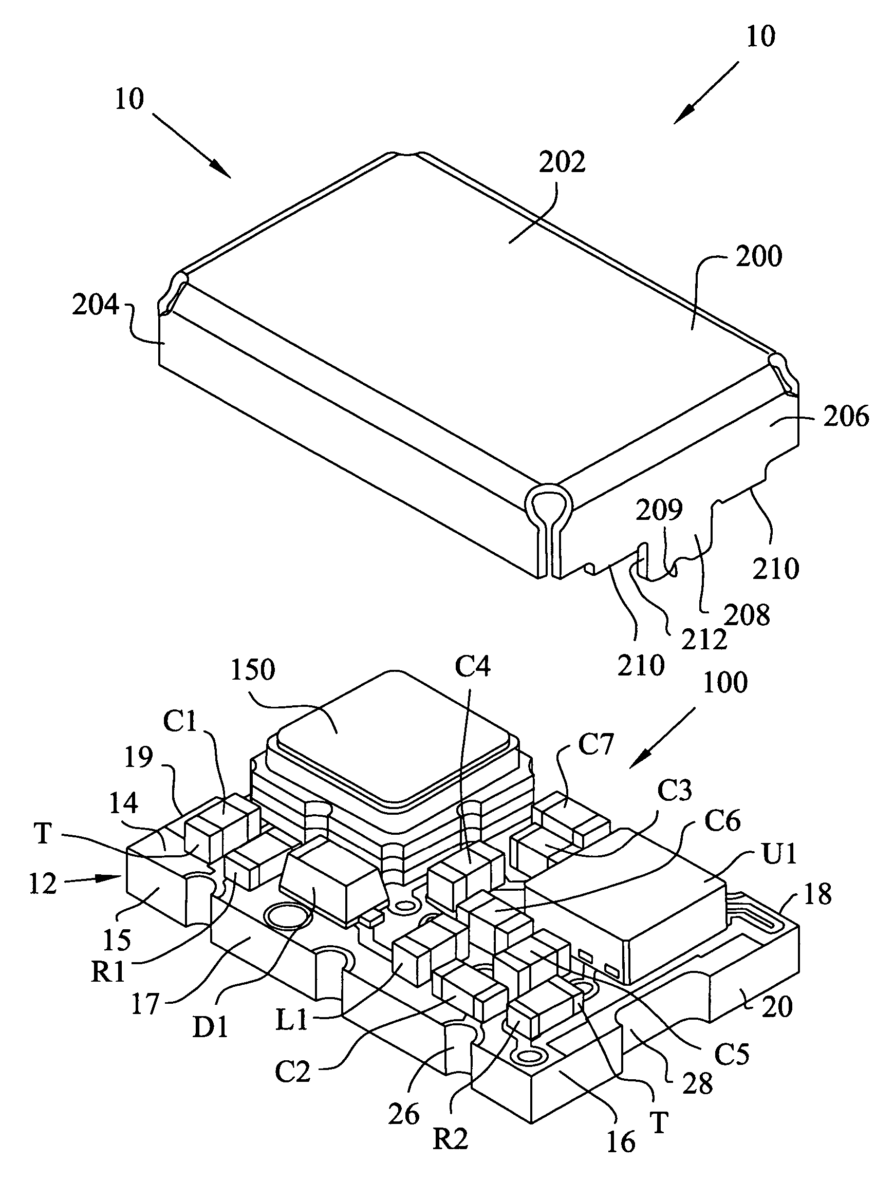
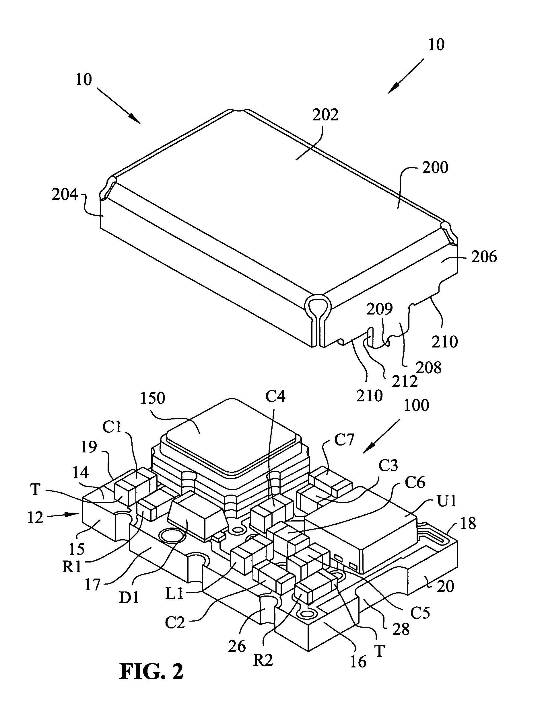
[0049]Referring to FIG. 8, an alternative embodiment of a voltage controlled surface acoustic wave oscillator (VCSO) circuit 300 is shown. VCSO circuit 300 includes a voltage controlled oscillator circuit 320 and a surface acoustic wave resonator device (SAW) 150.

[0050]Voltage controlled oscillator circuit 120 can comprise an integrated circuit U1. Integrated circuit U1 includes an amplifier, a signal conditioner and a LVPECL driver. Integrated circuit U1 can be a Texas Instruments part number SN65LVDS16 that is commercially available from Texas Instruments Corporation of Dallas, Tex. Integrated circuit U1 is a surface mount component that has nine (9) terminals or pads. Integrated circuit U1 has terminals T1, T2, T3, T4, T5, T6, T7, T8 and T9.

[0051]Terminal T1 is connected to power supply terminal Vcc. Power supply terminal Vcc can be set at 3.3 volts. Terminal T2 is connected to node N10. Terminal T3 is connected to node N11. Terminal T4 is connected to node N12 or ground. Termina...


PUM

PropertyMeasurementUnit
lengthaaaaaaaaaa
widthaaaaaaaaaa
widthaaaaaaaaaa

Abstract

A module for a surface acoustic wave oscillator includes a substrate having a top surface, a bottom surface and peripheral side faces. Several castellations are located about the outer peripheral side faces thereof. The castellations form an electrical connection between the top and bottom surfaces of the substrate. Connection pads are mounted on the top surface and are adapted for connection to the castellations. An oscillator circuit and a surface acoustic wave device are mounted on the top surface and connected to the connection pads. A cover is mounted over the substrate and has at least one tab adapted to be fitted within a respective one of the castellations. The overall module with the cover has a dimension of approximately 5 mm in width, 7 mm in length, and 2.7 mm in height.

Description

FIELD OF THE INVENTION[0001]This invention relates to oscillators and, in particular, to a voltage controlled surface acoustic wave oscillator (VCSO).DESCRIPTION OF THE RELATED ART[0002]High capacity data networks rely on signal repeaters and sensitive receivers for low-error data transmission. To decode and / or cleanly retransmit a serial data signal, such networks include components which create a data timing signal having the same phase and frequency as the data signal. This step of creating a timing signal has been labeled “clock recovery.”[0003]Data clock recovery requires a relatively high purity reference signal to serve as a starting point for matching the serial data signal clock rate and also requires circuitry for frequency adjustment. The type, cost and quality of the technology employed to generate the high purity reference signal vary according to the class of data network application. For fixed large-scale installations, an “atomic” clock may serve as the ultimate sour...

Claims


Application Information

Patent Timeline
Patent Type & Authority Patents(United States)
IPC IPC(8): H03B5/36
CPCH03B5/32H03B5/326H05K1/165H05K3/3405H05K1/0237H05K3/403H05K2201/0162H05K2201/0209H05K2201/09181H05K2201/09263H05K2201/10371
Inventor KNECHT, THOMAS A.JACOBSON, ROBERT A.
Owner CTS CORP ELKHART
Why Eureka
Try Eureka